How Close and Spaced Winding Affect Inductor Parasitic Capacitance and Frequency Response
 2026.11.8
 Articles
 GOTREND
1、Q & A
Q1: What is the difference between close winding and spaced winding in inductors?
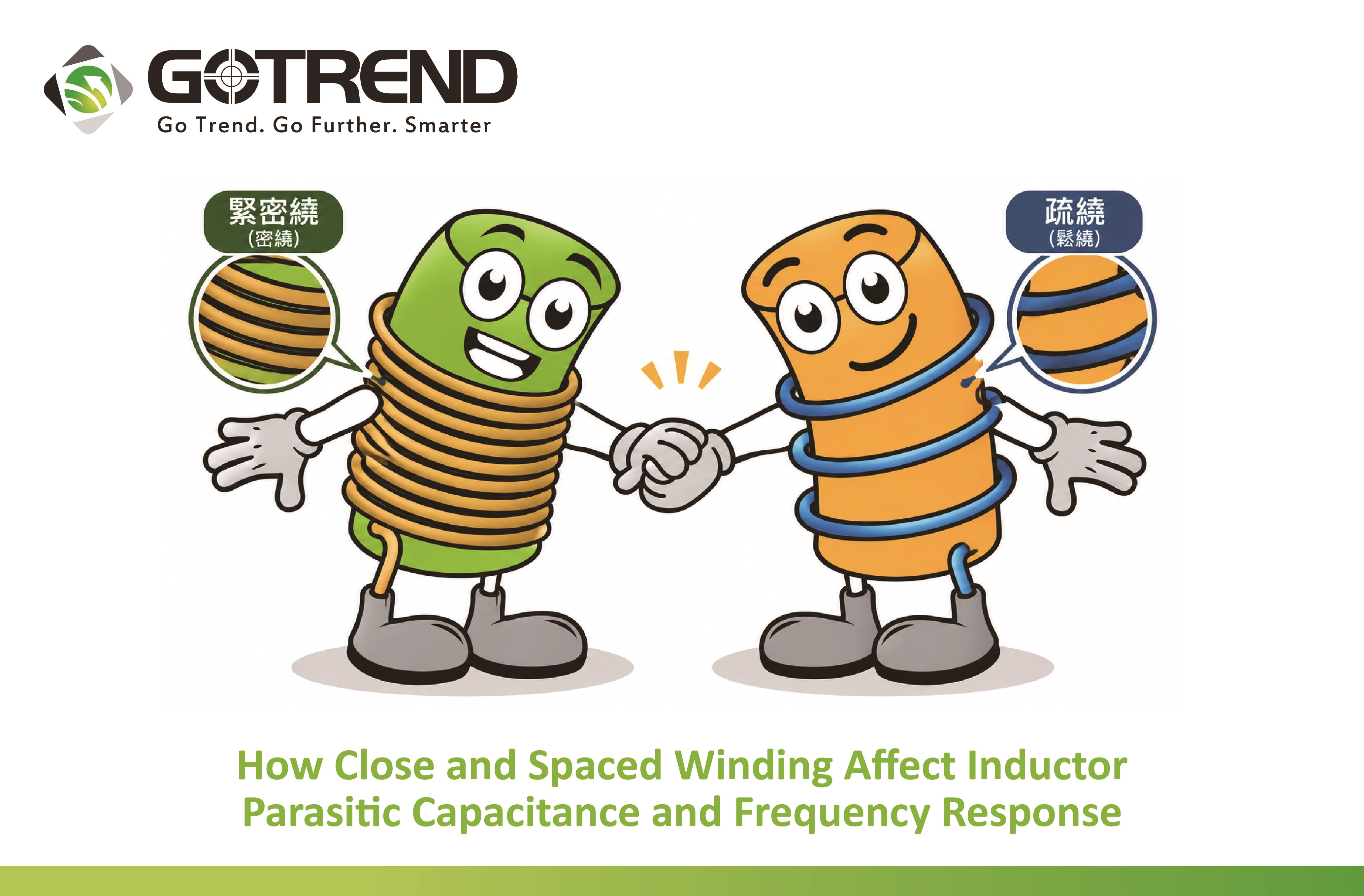
A: Close winding is a winding method in which adjacent turns are arranged tightly together with minimal spacing, providing higher winding space utilization. Spaced winding, on the other hand, maintains a defined distance between adjacent turns and can be used to adjust the parasitic capacitance characteristics of the winding.
Q2: Why can spaced winding improve the high-frequency characteristics of inductors?
A: When inductance (L) remains approximately the same and the effective parasitic capacitance is successfully reduced, increasing the spacing between adjacent turns can decrease capacitive coupling. This may increase the self-resonant frequency (SRF) and extend the frequency range over which the inductor exhibits inductive behavior. The actual improvement must be verified through measurements.
Q3: What quality risks may arise from inconsistent winding spacing during mass production?
A: Three major quality and reliability risks should be considered: variations in parasitic capacitance that cause differences in high-frequency performance between production batches, inter-turn insulation failures resulting from improper winding tension or insulation damage, and unexpected temperature rise caused by thermal management issues.
1. Basic Concepts of Close and Spaced Winding
Close winding and spaced winding are two common winding methods used in inductor design. Different winding arrangements may affect the parasitic capacitance and frequency response of an inductor.
In close winding, each turn is positioned directly next to the preceding turn, resulting in higher winding space utilization. Under the same winding space and other design conditions, close winding generally allows more turns to be accommodated, which helps achieve higher inductance (L). This method is commonly used in low-frequency filtering applications where compact size and relatively high inductance are required.
In spaced winding, a defined gap is intentionally maintained between adjacent turns, for example, by adjusting the winding pitch of an automated winding machine. Under the same available winding length and wire diameter, increasing the spacing may reduce the number of turns that can be accommodated. However, this approach helps adjust the parasitic capacitance characteristics of the winding and is one possible method for improving high-frequency performance.
《圖示1》
2. Winding Spacing and Parasitic Capacitance
An inductor winding consists of multiple turns of insulated wire. Because a potential difference exists between adjacent conductors, a small amount of inter-turn capacitance is formed. This capacitance is influenced by the distance between conductors and the dielectric properties of the insulation material.
However, inter-turn capacitance is only one contributor to the effective parasitic capacitance (Cp) of an inductor. The overall effective parasitic capacitance is also influenced by wire diameter, number of turns, number of winding layers, insulation materials, winding arrangement, and capacitive coupling between the winding, magnetic core, and surrounding conductors.
When other design conditions remain similar, appropriately increasing the spacing between adjacent turns generally helps reduce capacitive coupling. However, the actual improvement depends on the winding structure and must be confirmed through measurements.
3. Parasitic Capacitance and Frequency Response
In addition to inductance (L), a practical inductor also exhibits effective parasitic capacitance (Cp). These characteristics give rise to a phenomenon known as self-resonance, which occurs at the self-resonant frequency (SRF).
Using a simplified equivalent circuit model, the SRF can be approximated as:
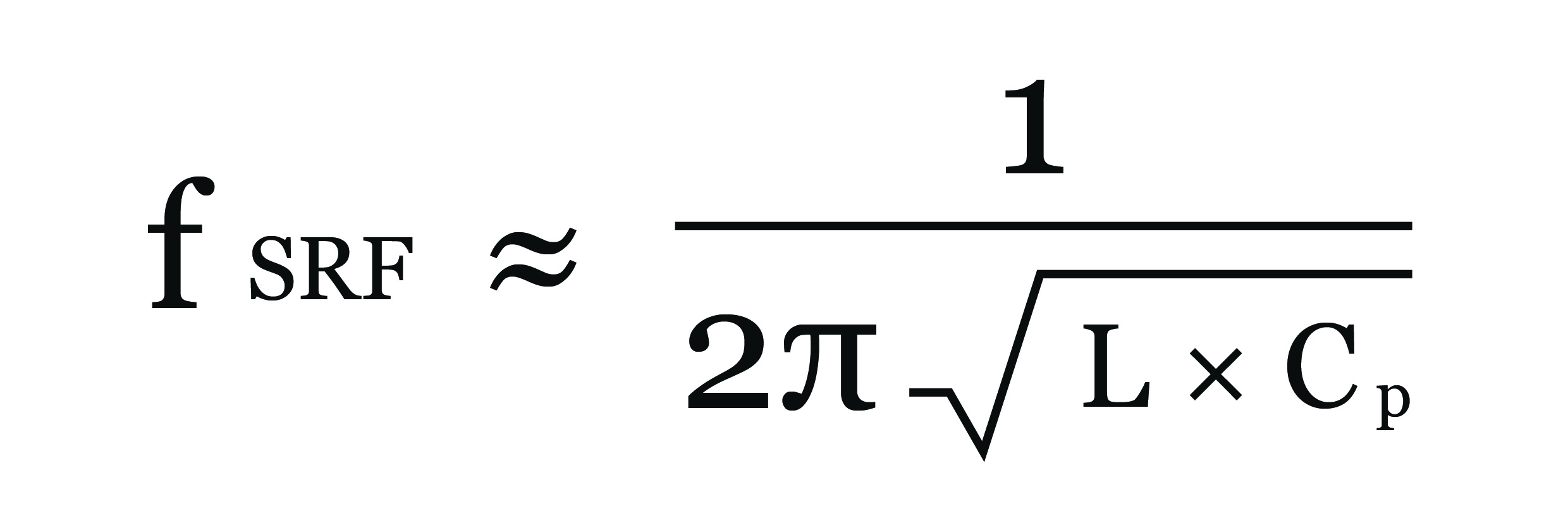
Where:
A: Close winding is a winding method in which adjacent turns are arranged tightly together with minimal spacing, providing higher winding space utilization. Spaced winding, on the other hand, maintains a defined distance between adjacent turns and can be used to adjust the parasitic capacitance characteristics of the winding.
Q2: Why can spaced winding improve the high-frequency characteristics of inductors?
A: When inductance (L) remains approximately the same and the effective parasitic capacitance is successfully reduced, increasing the spacing between adjacent turns can decrease capacitive coupling. This may increase the self-resonant frequency (SRF) and extend the frequency range over which the inductor exhibits inductive behavior. The actual improvement must be verified through measurements.
Q3: What quality risks may arise from inconsistent winding spacing during mass production?
A: Three major quality and reliability risks should be considered: variations in parasitic capacitance that cause differences in high-frequency performance between production batches, inter-turn insulation failures resulting from improper winding tension or insulation damage, and unexpected temperature rise caused by thermal management issues.
1. Basic Concepts of Close and Spaced Winding
Close winding and spaced winding are two common winding methods used in inductor design. Different winding arrangements may affect the parasitic capacitance and frequency response of an inductor.
In close winding, each turn is positioned directly next to the preceding turn, resulting in higher winding space utilization. Under the same winding space and other design conditions, close winding generally allows more turns to be accommodated, which helps achieve higher inductance (L). This method is commonly used in low-frequency filtering applications where compact size and relatively high inductance are required.
In spaced winding, a defined gap is intentionally maintained between adjacent turns, for example, by adjusting the winding pitch of an automated winding machine. Under the same available winding length and wire diameter, increasing the spacing may reduce the number of turns that can be accommodated. However, this approach helps adjust the parasitic capacitance characteristics of the winding and is one possible method for improving high-frequency performance.
《圖示1》
2. Winding Spacing and Parasitic Capacitance
An inductor winding consists of multiple turns of insulated wire. Because a potential difference exists between adjacent conductors, a small amount of inter-turn capacitance is formed. This capacitance is influenced by the distance between conductors and the dielectric properties of the insulation material.
However, inter-turn capacitance is only one contributor to the effective parasitic capacitance (Cp) of an inductor. The overall effective parasitic capacitance is also influenced by wire diameter, number of turns, number of winding layers, insulation materials, winding arrangement, and capacitive coupling between the winding, magnetic core, and surrounding conductors.
When other design conditions remain similar, appropriately increasing the spacing between adjacent turns generally helps reduce capacitive coupling. However, the actual improvement depends on the winding structure and must be confirmed through measurements.
3. Parasitic Capacitance and Frequency Response
In addition to inductance (L), a practical inductor also exhibits effective parasitic capacitance (Cp). These characteristics give rise to a phenomenon known as self-resonance, which occurs at the self-resonant frequency (SRF).
Using a simplified equivalent circuit model, the SRF can be approximated as:
Where:
- L: Approximate equivalent inductance.
- Cp: Approximate equivalent parasitic capacitance.
- fSRF: Self-resonant frequency.
In practical components, losses, distributed effects, and multiple resonances may influence the frequency response. Therefore, the actual SRF should be confirmed through measurements.
For a typical inductor, the component generally exhibits inductive behavior at frequencies below its first self-resonant frequency. As the operating frequency approaches the SRF, its impedance characteristics change significantly.
In a simplified single-resonance model, the inductor generally exhibits capacitive behavior above the first SRF. However, actual components may exhibit additional resonances.
Therefore, in high-frequency circuit design, it is important to evaluate not only inductance and DC resistance (DCR) but also the impedance-frequency characteristics and SRF within the intended operating frequency range. This helps prevent parasitic effects from adversely affecting circuit performance.
Adjusting winding spacing is one possible approach to improving parasitic capacitance and frequency response. Nevertheless, the effectiveness of this method must be evaluated together with the magnetic core, winding configuration, and overall circuit conditions.
4. Design Trade-Offs Between Close and Spaced Winding
Both close winding and spaced winding offer distinct design advantages.
Close winding provides higher winding space utilization, while spaced winding allows designers to adjust inter-turn spacing and potentially improve parasitic capacitance characteristics in certain winding configurations.
The winding method should not be selected based solely on operating frequency. Instead, the number of turns, available space, high-frequency parasitic effects, and magnetic core structure should all be considered.
For automotive electronics applications, AEC-Q200 specifies stress test qualification requirements for passive components. It does not prescribe a particular winding spacing or winding method. Therefore, the winding configuration must still be designed and validated according to the actual electrical and environmental requirements.
Comparison of Close and Spaced Winding
5. Manufacturing Process Control and Quality Verification
Winding spacing affects not only the electrical characteristics of an inductor but also manufacturing consistency and long-term reliability. Three key aspects should be considered during mass production.
(1) Electrical Performance Consistency
Variations in winding tension, inter-turn spacing, and wire positioning may affect inductance, parasitic capacitance, and high-frequency impedance characteristics. These variations can lead to performance differences between production batches.
(2) Inter-Turn Insulation Reliability
Improper winding tension, wire abrasion, overlapping or crossing turns, and insulation damage during winding may increase the risk of insulation failure, including inter-turn short circuits.
Appropriate process controls and verification requirements should be established according to the product's operating voltage, temperature, and environmental conditions.
(3) Temperature Rise and Thermal Management
Winding arrangement may influence conductor losses and heat dissipation paths. However, actual temperature rise also depends on wire diameter, current, magnetic core losses, packaging structure, and environmental conditions.
Temperature rise testing should therefore be conducted to verify whether the design meets the intended application requirements.
Electrical Performance Verification
When comparing close winding and spaced winding, consistent test conditions should be established according to the purpose of the evaluation.
Recommended measurements include:
By comparing the measurement results of the two winding methods, engineers can assess the effects of winding spacing on inductor performance and determine whether the design meets the requirements of the intended application.
6. Conclusion
Both close winding and spaced winding have their respective advantages.
Close winding helps improve winding space utilization, while spaced winding allows inter-turn spacing to be adjusted to improve parasitic capacitance characteristics in certain designs.
However, the high-frequency performance of an inductor depends not only on winding spacing but also on magnetic core materials, number of turns, winding structure, AC losses, and operating frequency.
Therefore, inductor design should consider inductance, DC resistance, self-resonant frequency, impedance characteristics, and temperature rise.
Through appropriate process control and measurement verification, manufacturers can ensure that their inductors meet application requirements while maintaining consistent performance during mass production.
If you are interested in our products, please Contact Us: service@gotrend.com.tw
For a typical inductor, the component generally exhibits inductive behavior at frequencies below its first self-resonant frequency. As the operating frequency approaches the SRF, its impedance characteristics change significantly.
In a simplified single-resonance model, the inductor generally exhibits capacitive behavior above the first SRF. However, actual components may exhibit additional resonances.
Therefore, in high-frequency circuit design, it is important to evaluate not only inductance and DC resistance (DCR) but also the impedance-frequency characteristics and SRF within the intended operating frequency range. This helps prevent parasitic effects from adversely affecting circuit performance.
Adjusting winding spacing is one possible approach to improving parasitic capacitance and frequency response. Nevertheless, the effectiveness of this method must be evaluated together with the magnetic core, winding configuration, and overall circuit conditions.
4. Design Trade-Offs Between Close and Spaced Winding
Both close winding and spaced winding offer distinct design advantages.
Close winding provides higher winding space utilization, while spaced winding allows designers to adjust inter-turn spacing and potentially improve parasitic capacitance characteristics in certain winding configurations.
The winding method should not be selected based solely on operating frequency. Instead, the number of turns, available space, high-frequency parasitic effects, and magnetic core structure should all be considered.
For automotive electronics applications, AEC-Q200 specifies stress test qualification requirements for passive components. It does not prescribe a particular winding spacing or winding method. Therefore, the winding configuration must still be designed and validated according to the actual electrical and environmental requirements.
Comparison of Close and Spaced Winding
Parameter |
Close Winding |
Spaced Winding |
Inter-turn spacing |
Smaller |
Larger |
Space utilization |
Generally higher |
Generally lower within the same available space |
Number of turns |
Generally accommodates more turns within a fixed space |
Generally accommodates fewer turns within a fixed space |
Effective parasitic capacitance |
May be higher |
May be lower with appropriate design |
Self-resonant frequency (SRF) |
Influenced by both inductance and parasitic capacitance |
May increase when L remains similar and Cp is reduced |
Thermal performance / AC losses |
Depends on winding structure and operating environment |
Depends on winding structure and operating environment |
Key quality control factors |
Winding tension, wire arrangement, and insulation integrity |
Turn spacing, winding tension, wire arrangement, and insulation integrity |
5. Manufacturing Process Control and Quality Verification
Winding spacing affects not only the electrical characteristics of an inductor but also manufacturing consistency and long-term reliability. Three key aspects should be considered during mass production.
(1) Electrical Performance Consistency
Variations in winding tension, inter-turn spacing, and wire positioning may affect inductance, parasitic capacitance, and high-frequency impedance characteristics. These variations can lead to performance differences between production batches.
(2) Inter-Turn Insulation Reliability
Improper winding tension, wire abrasion, overlapping or crossing turns, and insulation damage during winding may increase the risk of insulation failure, including inter-turn short circuits.
Appropriate process controls and verification requirements should be established according to the product's operating voltage, temperature, and environmental conditions.
(3) Temperature Rise and Thermal Management
Winding arrangement may influence conductor losses and heat dissipation paths. However, actual temperature rise also depends on wire diameter, current, magnetic core losses, packaging structure, and environmental conditions.
Temperature rise testing should therefore be conducted to verify whether the design meets the intended application requirements.
Electrical Performance Verification
When comparing close winding and spaced winding, consistent test conditions should be established according to the purpose of the evaluation.
Recommended measurements include:
- Inductance (L): To evaluate inductance characteristics.
- DC Resistance (DCR): To evaluate the winding's DC resistance.
- Impedance-Frequency Response: To evaluate impedance characteristics across the target frequency range.
- Self-Resonant Frequency (SRF): To identify the frequency at which self-resonance occurs.
- AC Resistance (ACR): To evaluate AC resistance characteristics associated with conductor losses, when necessary.
- Temperature Rise: To assess thermal performance under specified operating conditions, when necessary.
By comparing the measurement results of the two winding methods, engineers can assess the effects of winding spacing on inductor performance and determine whether the design meets the requirements of the intended application.
6. Conclusion
Both close winding and spaced winding have their respective advantages.
Close winding helps improve winding space utilization, while spaced winding allows inter-turn spacing to be adjusted to improve parasitic capacitance characteristics in certain designs.
However, the high-frequency performance of an inductor depends not only on winding spacing but also on magnetic core materials, number of turns, winding structure, AC losses, and operating frequency.
Therefore, inductor design should consider inductance, DC resistance, self-resonant frequency, impedance characteristics, and temperature rise.
Through appropriate process control and measurement verification, manufacturers can ensure that their inductors meet application requirements while maintaining consistent performance during mass production.
If you are interested in our products, please Contact Us: service@gotrend.com.tw