Analysis of the Relationship between Inductor Q-Factor and ACR
![]() 2023.11.8
2023.11.8
 Articles
 GOTREND Technology Co.,Ltd
Q value definition
The Q-factor, also known as the quality factor, is a primary parameter used to measure inductive components. It represents the ratio of inductive reactance to equivalent loss resistance when an inductive component operates at a specific frequency under AC voltage.
The higher the Q-factor of an inductive component, the lower its losses and the higher its operational efficiency. The Q-factor is directly related to factors such as the DC resistance of the coil wire, dielectric losses in the coil's core, and losses caused by materials like the iron core and shielding covers.
Calculation of Q value and ACR
At a certain frequency, the quality factor is actually the ratio of inductive reactance to resistance in a inductor, i.e., the ratio of the imaginary part (XL) to the real part (RL) of impedance, as shown in formula (1).
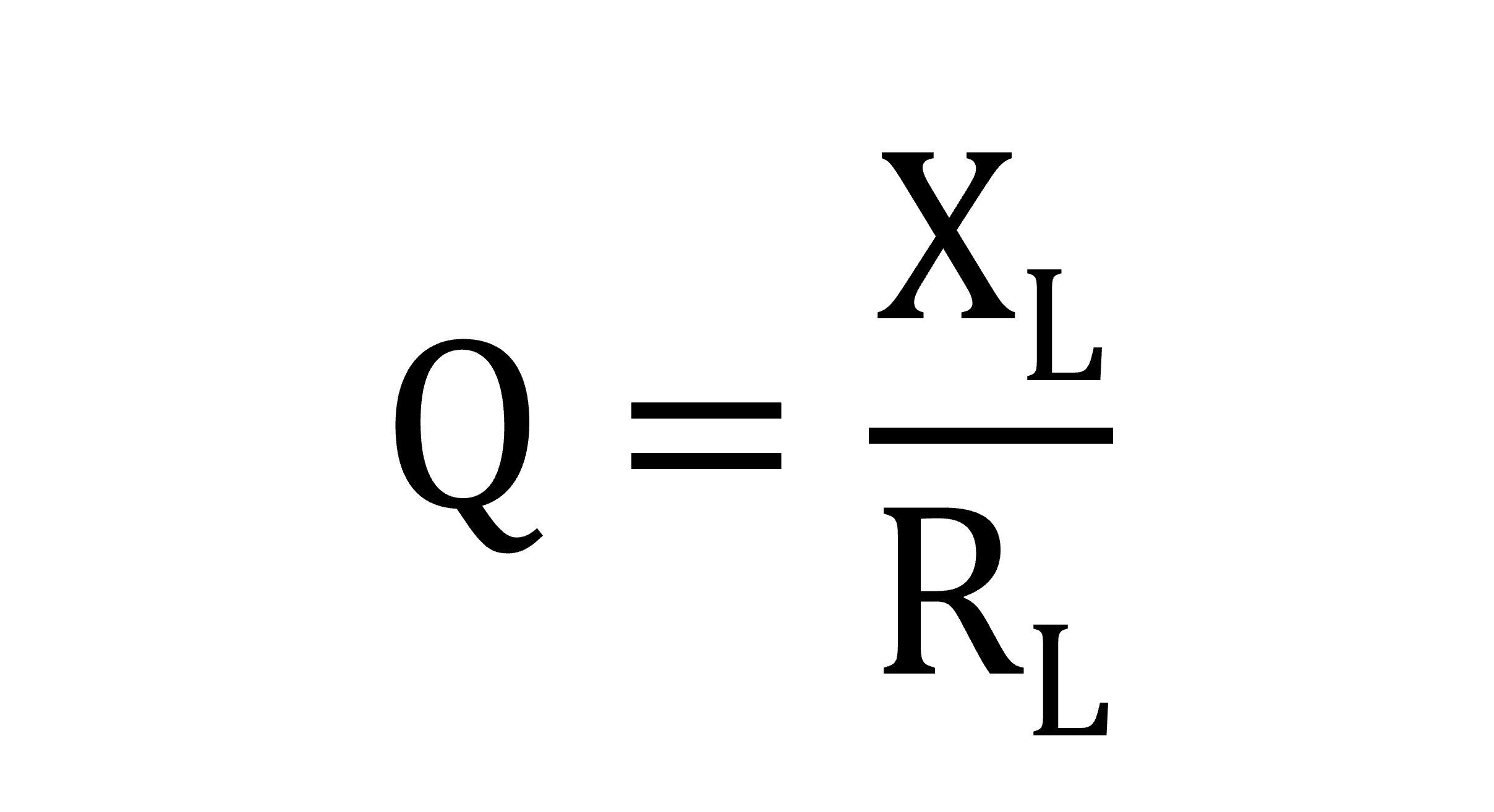
Where XL is the inductive reactance of the inductor, and RL is the AC resistance of the inductor.
Discussion on the influencing factors of Q value and ACR
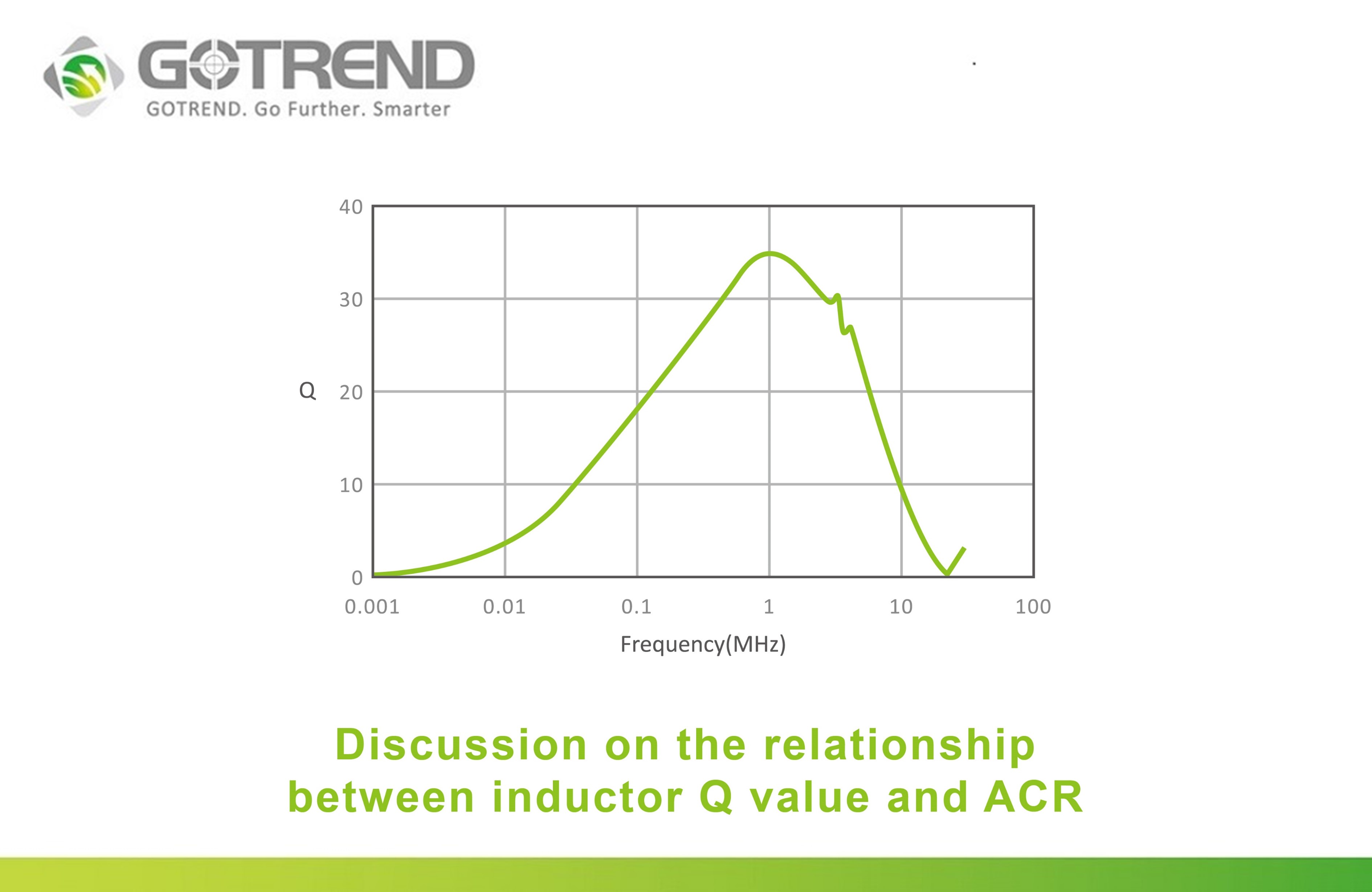
At lower frequencies, the AC resistance is greater than the inductive reactance , resulting in a lower Q-factor. However, as the operating frequency increases, the inductive reactance, approximately equal to 2πfL, becomes larger. Even though resistance increases due to skin effect and proximity effect, the Q-factor increases with the rising operating frequency.
As it approaches the Self-Resonant Frequency point, the inductive reactance gradually diminishes due to the counteraction of capacitive reactance, resulting in a gradual decrease in the Q-factor. At the SRF point, it becomes zero because the inductive reactance and capacitive reactance cancel each other out.
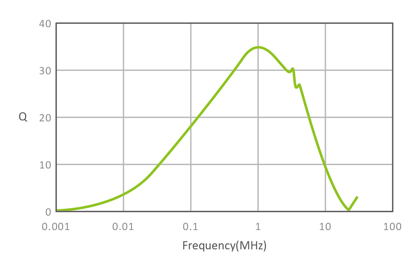
FIG. 2 : Relationship between Q value and frequency of GOTREND GNR4018P-220M Inductor
In the operating frequency band of the inductor application, the higher the Q value, the better; It means that its inductive reactance is much larger than the AC resistance. So in general, the Q value should preferably be above 40, This indicates that the quality of the inductor at this time is in good condition.
However, as the DC bias current increases, the inductance value decreases and its Q value decreases. Therefore, if the inductor is wound with flat enameled wire or multi-stranded enameled wire, the skin effect can be reduced, that is, the AC resistance is reduced, that is, the Q value of the inductor can be increased.
DC resistance is generally considered to be the DC resistance value of the conductor enameled wire, and this DC resistance can be calculated according to the outer diameter of the conductor enameled wire and its length. However, most of the low-current SMD inductors will use laser welding SMD guides at the winding terminal, because the number of winding turns is small and the wire length is not long, the DC resistance value is not very high. Therefore, the resistance value of the welding interface often accounts for a large proportion of the overall DC resistance.
Taking GOTREND's wirewound SMD inductor GSBS6045P-1R5N as an example, its measured DC resistance is 14.6mΩ , while the DC resistance calculated by wire diameter and length is 12.1mΩ. The results show that this welding resistance accounts for about 17% of the overall DC resistance.
AC resistance will cause AC resistance to increase with operating frequency due to skin effect and proximity effect ; From the analysis of common applications of general power inductors, because the AC component is much lower than the DC component, the effect of AC resistance ACR is not obvious ; However, at light loads, the loss caused by the AC value ACR cannot be ignored because the DC component is reduced.
The skin effect is that under the condition of alternating, the current distribution inside the conductor is uneven and concentrated on the surface of the wire, causing the cross-sectional area of the equivalent conductor to decrease, which in turn increases the equivalent resistance of the wire with frequency.
In addition, in a wire winding, adjacent wires will add and subtract the magnetic field due to the current , so that the current is concentrated on the surface adjacent to the wire (or the farthest surface, depending on the direction of the current) , which also causes the equivalent wire cross-sectional area to decrease and the equivalent resistance to increase, that is, the so-called proximity effect ; In an inductive application with multiple windings, the proximity effect is even more pronounced.
Related articles :
• What is the difference between lead-free solder and leaded solder ?
• Appearance Differences and Structural Recognition of Iron Cores
• The role of NTC and the phenomenon of abnormalities