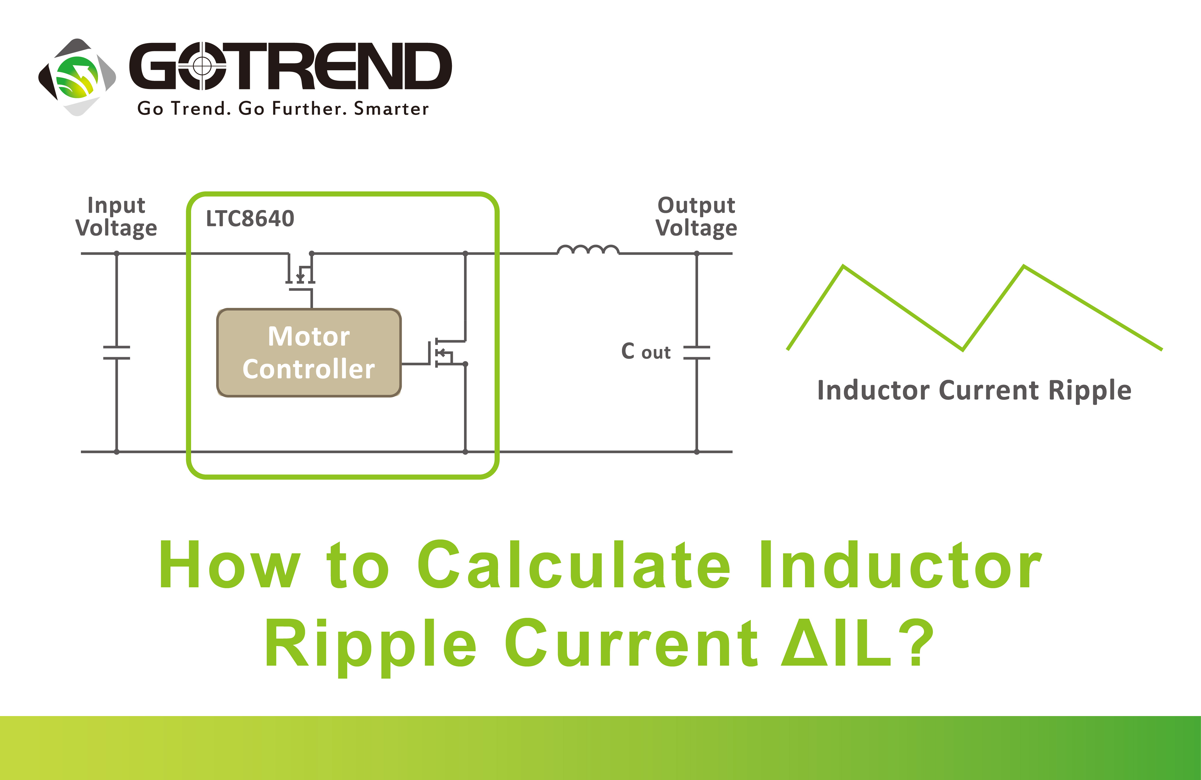
How to Calculate Inductor Ripple Current ΔIL?
![]() 2024.5.3
2024.5.3
 Articles
 GOTREND Technology Co., Ltd.
1、What is current ripple rate "r"
The current ripple rate indicates the proportion between the AC component and the DC component of the inductor.
2、 Calculation of current ripple rate
In DC-DC topology circuits, the inductor component is the most crucial. Among the various parameters of the inductor during circuit design, the current ripple rate r is the most fundamental and influential parameter. It signifies the ratio of AC component to DC component in the inductor, and can be expressed by the following formula :

In the formula,
r :Inductor current ripple rate.
IAC:AC current
ΔI :incremental current,
IDC:DC current.
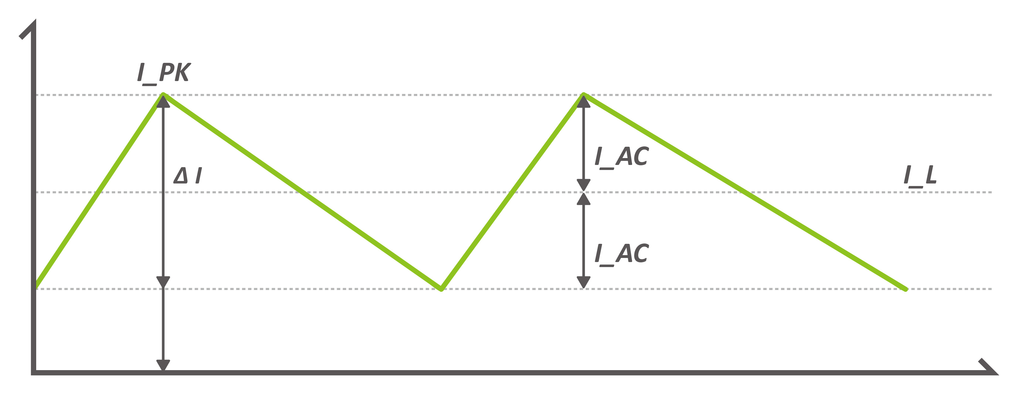
Figure 1:Continuous conduction mode
As shown in Figure 1, the ripple rate (r) of the current is only applicable in CCM (Continuous Conduction Mode), meaning it operates in continuous conduction mode, and there is a valid range of 0 – 2 (when r = 0, the inductance value is infinite, and when r = 2, IAC = IDC, at which point the switch topology transitions to critical conduction mode).
The IDC, as illustrated in the figure, corresponds to IL and is positioned at the geometric center of the figure. This formula is applicable to all topologies, including boost, buck, and buck-boost.
3、 Relationship between Current Ripple Rate (r) and Inductance Value
To understand the relationship between these two, we can derive it through the following formulas :
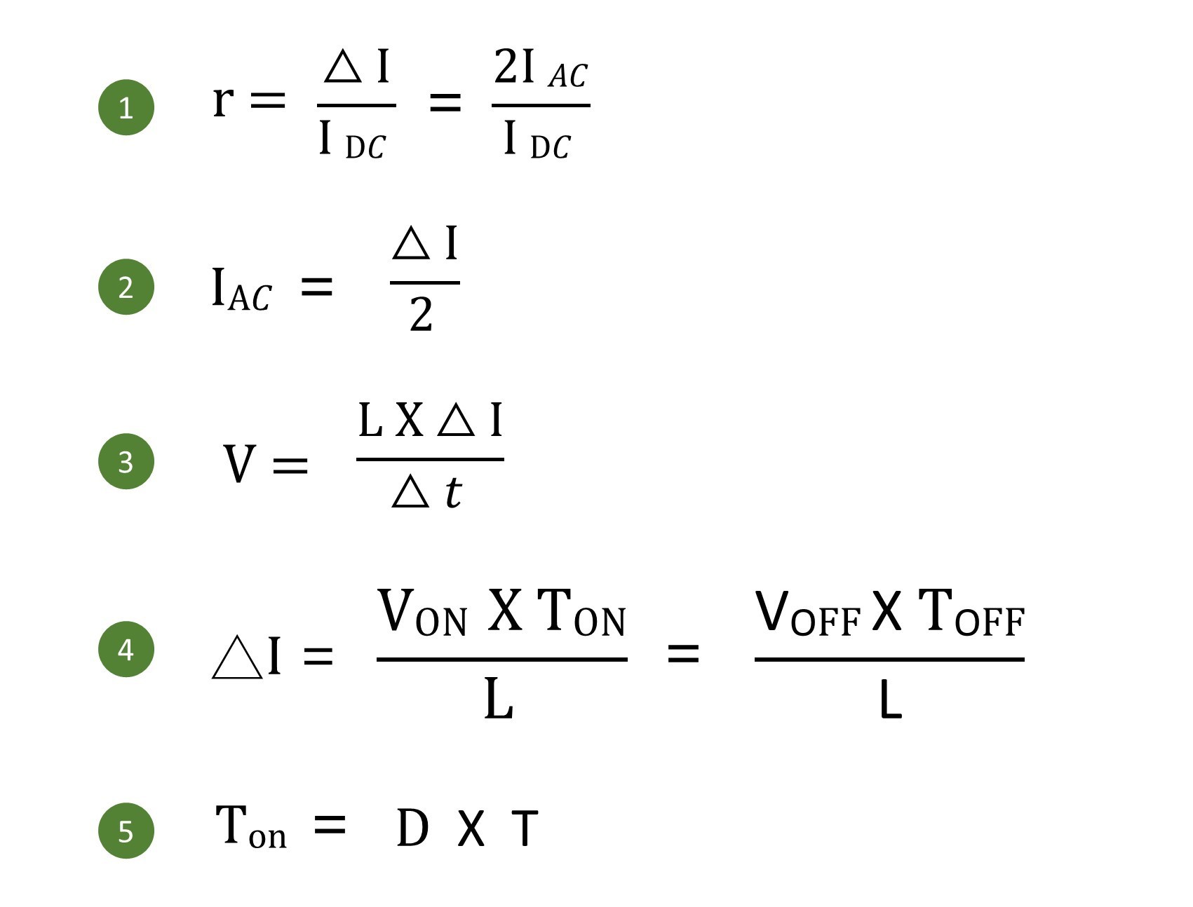
The above formula is introduced as follows :
• Formula (1) :
Represents the formula for inductance ripple rate, indicating the relationship between IAC and IDC in the inductor.
• Formula (2) :
Represents the relationship between the incremental current in the inductor and the AC component (IAC).
• Formula (3) :
This formula describes the relationship between the induced voltage in the inductor, the incremental current in the inductor, and time. It is a crucial equation used to characterize the steady state of the inductor.
• Formula (4) :
Derived from Formula (3), this equation is employed to depict the equal volt-second product during the on and off phases of the switch topology in a steady state.
• Formula (5) :
This formula expresses the relationship between the on-time of the switch, the duty cycle (D), and the period (T) in the context of the switch being in the conducting state.
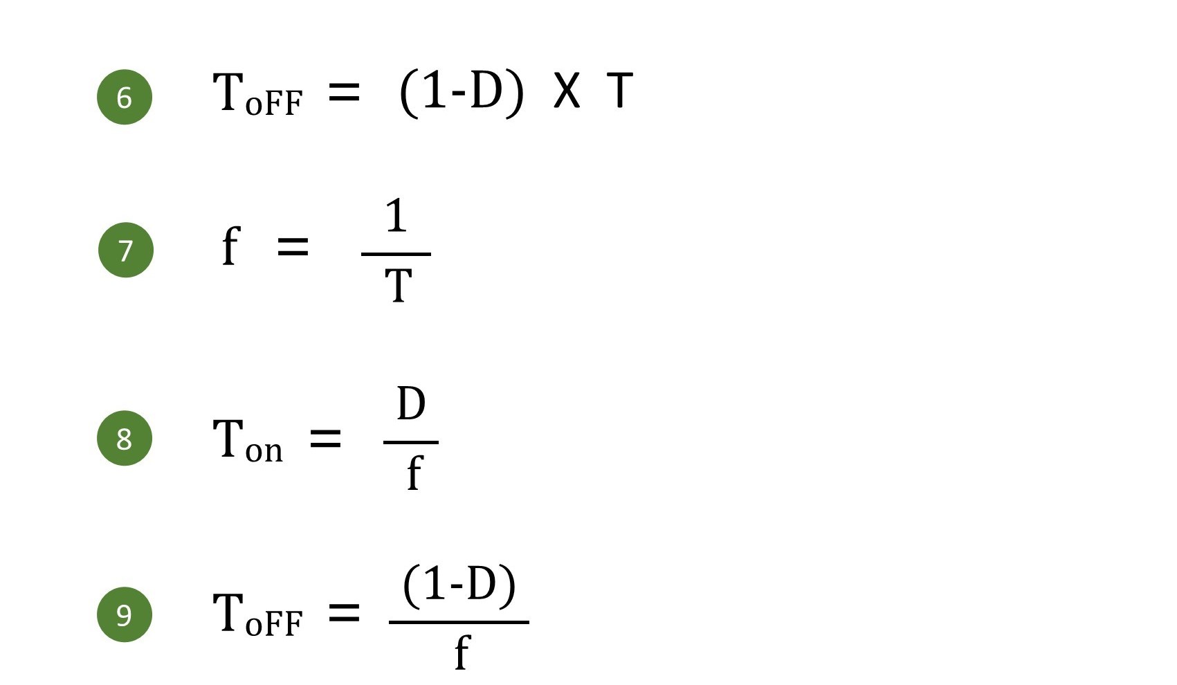
• Formula (6) :
Represents the relationship between the off-time of the switch, duty cycle (D), and the period (T).
• Formula (7) :
Represents the relationship between the switch frequency and the period.
• Formula (8) :
Derived by simultaneously solving Formula (5) and Formula (7), representing the relationship between the on-time, duty cycle, and switch frequency.
• Formula (9) :
Derived by simultaneously solving Formula (6) and Formula (7), representing the relationship between the off-time, duty cycle, and switch frequency.
After studying the above formulas, we obtain the final desired formula: the relationship between the current ripple rate (r) and the inductance value (L).
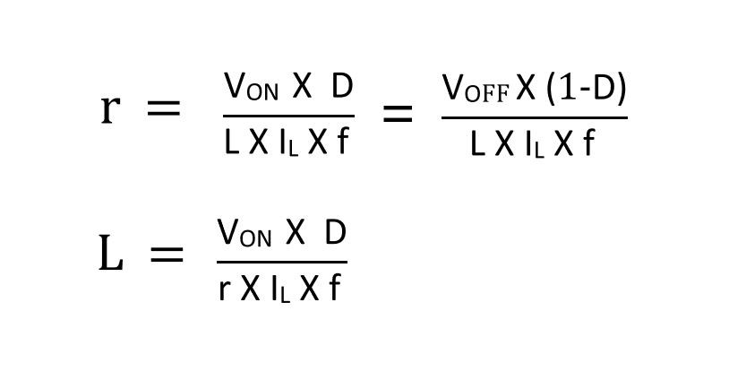
From this equation, we can observe that the ripple rate (r) of the inductor is not only related to the inductance but also depends on the input voltage, duty cycle, load current, and switching frequency.
4、 How to Choose the Inductance Current Ripple Rate (r)?
The design of almost all power inductors typically begins with the selection of the r value. In practical design, r values are generally chosen based on empirical values. From this perspective, the selection of r values is independent of specific operating conditions, switching frequencies, and even the topology itself.
The r value affects the current stress and losses of all power devices. Designers must consider a reasonable r value. By using the above formulas, selecting a suitable inductance value under specific operating conditions ensures that the r value falls within a reasonable and optimal range. This ensures that all parameters of our topology meet the design requirements.
In general, for various circuit topologies, the typical range for the r value is between 0.3 and 0.5. This range is based on considerations of inductor stress and size.
Additionally, the output capacitor is more sensitive to the AC component of the current. The capacitor eliminates the DC component, leaving the AC component as the primary source of capacitor losses. An increase in the current ripple ratio (r) similarly leads to an increase in the effective value of the current passing through the capacitor, resulting in increased losses. Of course, there are also associated losses between components such as switches, diodes, inductors, and "r," but their impact is minimal and will not be discussed here.
As shown in Figure 2 below, the approximate curves of energy and RMS current of the output capacitor concerning the ripple rate (r) are depicted. From the curves, we can observe that as the r value increases, the RMS current value of the output capacitor significantly rises.
Therefore, increasing the r value is highly unfavorable for the output capacitor, as it can easily lead to substantial power consumption, severe heating, and an impact on the efficiency of the inductor.
Additionally, it can be noted that when r is less than 0.4, reducing the r value can significantly decrease the energy-handling capacity of the inductor and reduce the size of the inductor. However, when r exceeds 0.4, the ability to handle energy does not vary significantly with changes in r. Based on the current analysis, choosing r within the range of 0.3 to 0.5 is undoubtedly a more reasonable choice.
.jpg)
Figure2. Effect of current ripple rate r on energy handling capability and output capacitance RMS.
5、 How to Correctly Choose Inductance Current Ripple?
Switching regulators convert input voltage to a higher or lower output voltage, requiring the use of an inductor to temporarily store electrical energy. The size of the inductor depends on the switching frequency of the switching regulator and the expected current flowing through the circuit.
How can one correctly choose the inductance value? This can be determined using commonly used formulas that include the inductance current ripple.
In most data sheets, application notes, and other instructional texts for buck regulators, it is recommended to keep the inductor current ripple at around 30% of the rated load. This implies that, under the rated load current, the inductor current peak and valley are respectively 15% higher and 15% lower than the average current. Why is choosing a 30% inductor current ripple or current ripple ratio (CR) considered a reasonable compromise?
For buck converters, such as the one illustrated in Figure 3 below, the following formula applies :
.jpg)
Figure 3. Corresponding inductor current ripple when using a buck converter.

This formula calculates the required inductance value (L) for a step-down converter based on the current ripple ratio (CR).
This ratio is typically specified as 0.3, or 30% peak ripple. In this formula, D represents the duty cycle, and T represents the period, depending on their respective switching frequencies.
Related articles :
• GOTREND 【GSFT-Series】molded power inductor-Your ultimate choice for compact switch-mode power supplies.
• DDR5 Inductor Solution-Low Loss, Achieving High Performance and Reliability.
• What requirements should the solder joints of lead-free solder meet?