What is a pulse transformer?
![]() 2024.2.19
2024.2.19
 Articles
 GOTREND Technology Co., Ltd.
1、What is a pulse transformer?
![]()
A pulse transformer utilizes magnetic saturation characteristics to convert input sinusoidal waves into narrow pulse wave outputs. Pulse transformers find applications in signal transmission (current isolation), low-power control circuits, and serve as key components in high-power switch-mode power supplies.
• Low-power pulse transformers are signal-oriented and commonly employed in digital logic and telecommunication circuits, such as Ethernet, typically used for matching logic drivers and transmission lines.
• Medium-power pulse transformers are used in power control circuits, for instance, in camera flash controllers.
• High-power pulse transformers are utilized in electrical distribution for electrical engineering purposes, while specialized high-voltage pulse transformers can be found in radar systems, particle accelerators, and similar applications.
2、Characteristics of a pulse transformer
(1) The job of a pulse transformer is in the transient state, when the pulse produces a square wave with a smooth top for a brief period of time.
(2) Pulse signals are periodic and exhibit voltage with either positive or negative polarity.
(3) Pulse transformers are required to maintain waveform integrity during transmission.
To minimize distortion of the pulse waveform to the greatest extent possible, pulse transformers pay special attention to keeping leakage inductance and distributed capacitance low, thus avoiding distortion. Most pulse transformers use closed-loop toroidal cores to reduce magnetic leakage caused by core joints.
3、Applications of a pulse transformer
Pulse transformers can be applied in gate drivers, trigger transformers, broadband transformers, or signal transformers. Similar to most transformers, pulse transformers can simultaneously provide functions such as pulse fidelity, voltage conversion, impedance matching, and isolation.
(1) Pulse transformers find widespread use in radar and signal conversion applications.
(2) Increasing or decreasing the pulse voltage changes the polarity of the pulse and is often paired with a common mode inductor.
(3) Isolate the secondary circuit from the primary circuit.
(4) Achieve greater coupling in transistor pulse oscillators.
(5) Multiple sets of secondary windings are used to obtain multiple sets of different pulses to create positive feedback between the plate and gate loops of a transistor, or between the collector and base of a transistor, in order to generate self-excited oscillations.
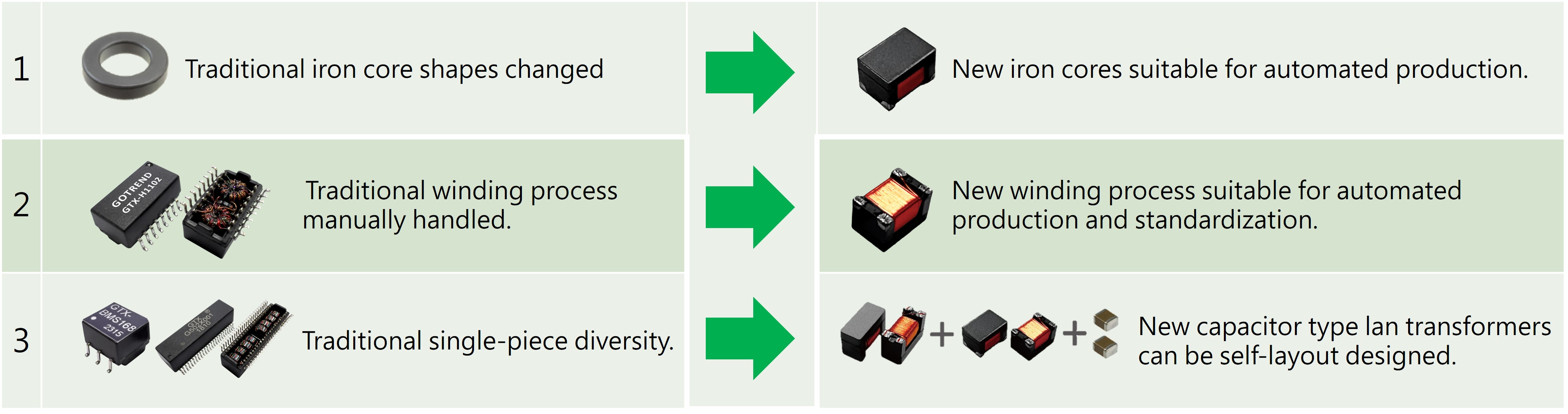
4、Comparison of traditional LAN transformers and new LAN transformers' advantages and disadvantages.
![]()
LAN pulse transformer module
![]()
![]()
GOTREND GTX-IH036 Lan Transformer Wiring Diagram
5、Pulse transformer circuit diagram
![]()
6、Applications of a pulse transformer in gate driver circuits.
Pulse conversion necessitates rectangular voltage pulses with fast rising and falling edges, and the frequency bandwidth must be sufficiently high to minimize acceptable levels of delay in signal transmission, while also minimizing significant distortion in the signal.
The frequency bandwidth and signal fidelity primarily depend on parameters such as capacitance between windings in the pulse transformer, self-capacitance of each winding, and equivalent resistance. These parameters can result in overshoot, undershoot, ringing, rise time, and fall time variations in the converted pulse.
GOTREND has developed an automated production surface-mount capacitive coupling transformer, replacing the complex functionality of traditional manually wound transformers.
Reference links:
https://www.gotrend.com.tw/ec99/rwd1606/news.asp?newsno=98
Related articles :
• New generation Capacitor Type Lan Transformer makes its debut, offering stable signal transmission and production automation.
• Analysis of the Relationship between Inductor Q-Factor and ACR
• What is transformer leakage inductance? What is sandwich winding?