What is transformer leakage inductance? What is sandwich winding?
![]() 2023.7.10
2023.7.10
 Articles

A 、 What is leakage inductance ?
The basic definition of a transformer is composed of a primary coil, a secondary coil and an iron core. The magnetic force generated by the primary winding cannot pass through the secondary coil during the coupling process between the primary and secondary windings, so the inductance with partial magnetic flux leakage is called leakage inductance.
The leakage inductance increases with higher frequencies. In general, at low operating frequencies such as 50Hz or 60Hz, the influence of leakage inductance can be ignored.
However, in modern switch-mode transformers, the operating frequencies are becoming higher and higher. For high-frequency transformers above 100kHz, the leakage inductance can cause the circuit to generate electromagnetic interference, resulting in overall interference noise in the switch-mode power supply. Therefore, it is crucial to reduce the impact of leakage inductance in the circuit.
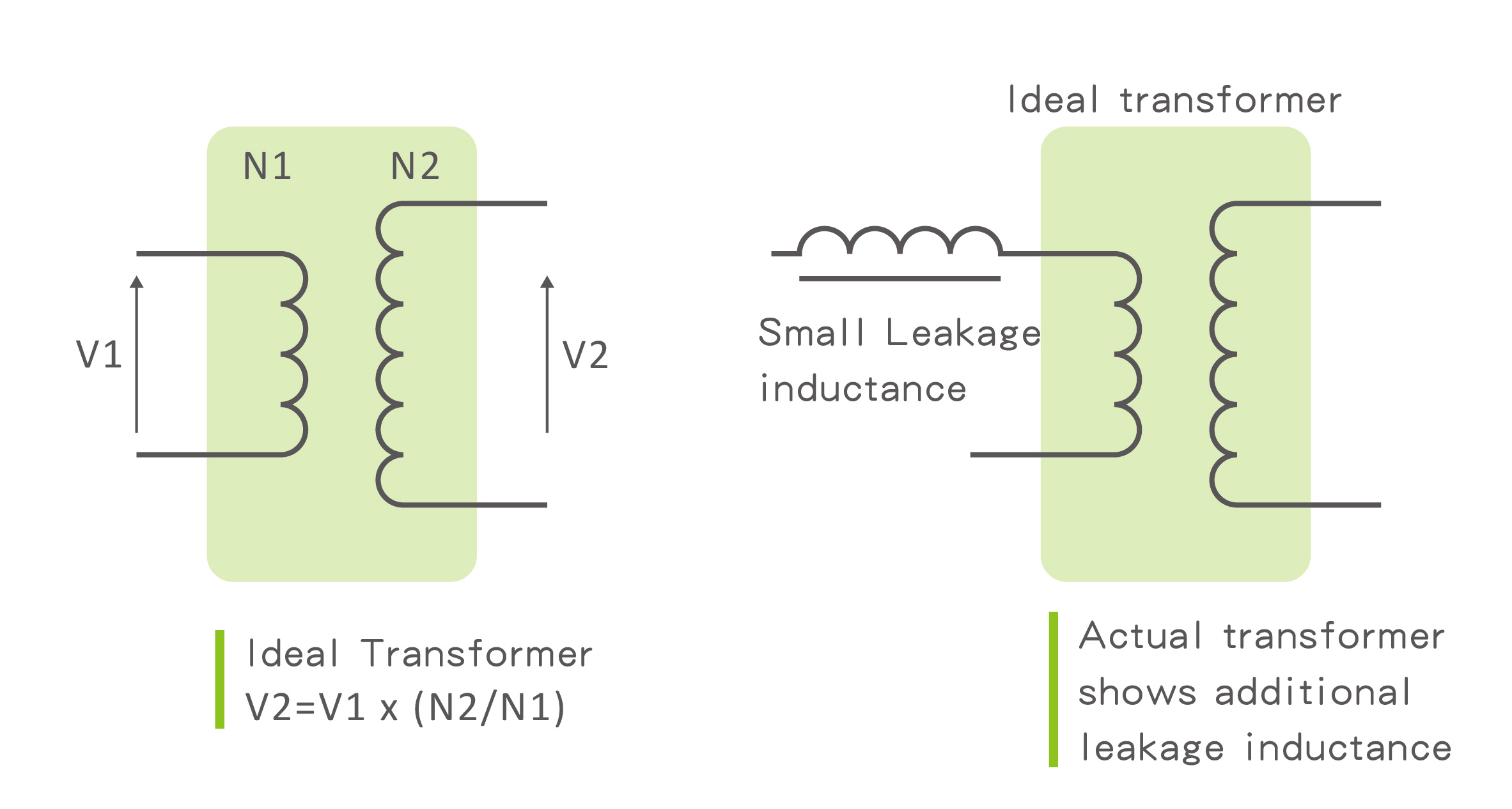
In an ideal transformer with no losses, the voltage ratio is directly the turns ratio and the current ratio is the inverse of the turns ratio (Figure 1). However, in actual design, the magnetic force generated by the primary coil will cause leakage inductance, and the leakage inductance can be expressed as the impedance of the leakage inductance in series with the coil (Figure 2).

The harm of leakage inductance lies in the generation of back electromotive force during the instant of transformer switch-off. If the leakage inductance is too large, it can easily cause breakdown of the switch components due to overvoltage.
Additionally, excessive leakage inductance can create oscillation loops with the circuit and the distributed capacitance of the transformer, leading to electromagnetic interference or decreased performance due to noise.
B 、 How to reduce leakage inductance ?
1. Reduce the number of turns of the primary coil
2. Increase the width of the winding slot and reduce the number of layers and height of the coil.
3. Increase the degree of coupling between the winding and the winding.
4. Select the iron core material with high magnetic permeability, high saturation strength and low loss.
5. Reduce the insulation thickness of the wire.
6. Winding structure using sandwich or sandwich winding method
7. Reduce the depth of the air gap
8. Primary and secondary coils need to be symmetrical or reduce the distance between the two.
C 、 Design of external resonant inductor and integrated resonant inductor
In the switch design, the smaller the leakage inductance, the better, because if the leakage inductance is too large, additional components are needed to improve it.
However, in the design of the LLC resonant transformer, instead increase the leakage inductance to replace the resonant inductance. There is no resonant inductance on the circuit board. Circuit cost is also reduced.
• Advantages of external resonant inductors :
It's a separate inductor, which is separate from the main transformer, flexible in design, can optimize the loss above the inductor, and can also adjust the transformer power ; The leakage inductance value of the general high-frequency transformer is designed to be very low, so it’s much smaller than the external resonant inductor, so the influence of the transformer on the resonant inductance isn’t very large, and it can generally be ignored.
• Disadvantages of external resonant inductance
The cost is higher than the integrated resonant inductor, because the resonant inductor is AC work, in order to reduce the loss of the core, the magnetic saturation value of the general iron core is relatively low, and the air gap of the GAP is larger, so that the eddy current loss of the resonant inductor is large, resulting in a relatively high temperature and a relatively large loss.
• Advantages of integrated resonant inductor
The cost is lower than the external resonant inductor, because the general integrated resonant inductor accounts for 20% of the main inductance, and the design of the leakage inductance needs to be particularly increased, and the coupling between the primary and secondary coils doesn’t need to be very good.
Generally, a double-slotted wire frame will be used to separate the primary and secondary rings, and the coil is simple to wrap around and the safety distance is better; The leakage inductance becomes larger, and the secondary parasitic capacitance becomes smaller, which is conducive to LLC design.
• Disadvantages of integrated resonant inductors
The volume of integrated transformer transformer is much larger than that of general transformer; Because the resonant inductor is the leakage inductance of the primary coil, the tolerance definition of the leakage inductance value, and the number of turns isn’t easy to adjust, the integrated resonant inductor is generally not too powerful, and most of the more than kilowatts use external resonant inductors.
D 、 Transformer sandwich winding method

In high-power transformers, in order to reduce the leakage inductance, the sandwich winding method is the most commonly used method. In a transformer, this is the primary clamped to the secondary, or the secondary clamped to the primary. It means that the primary is divided into 2 parts, first around the primary part, then around the second, and finally around the remaining part of the primary.
• Advantages of sandwich wrapping :
Increasing the area of primary and secondary coupling reduces the leakage inductance to improve efficiency, reduces the peak voltage generated by the leakage inductance when the MOSFET is turned off, and reduces the voltage stress of the MOSFET.
• Disadvantages of the sandwich wrapping method :
When the coupling area between the primary and secondary windings is increased, the distributed capacitance between the windings also increases. The inter-winding capacitance serves as the primary pathway for common-mode interference signals. Therefore, the sandwich winding configuration amplifies EMI interference.
E 、 How to test the leakage inductance?
When testing the leakage inductance, the test point is measured at the main inductance of the primary coil, and the other coil pins of the two feet of the primary coil are short-circuited in series.
At this time, the inductance value obtained by measuring the test point at the main inductance of the primary coil is the leakage Inductance value or self-inductance value.
Related articles:
• What is the principle of transformer and voltage conversion?
•What is copper loss? What is the skin effect ? The difference between Isat and Irms
• What is a high frequency transformer?
 GOTREND Technology Co.,Ltd


