What is a high frequency transformer?
![]() 2022.10.14
2022.10.14
 Articles
 GOTREND Technology Co.,Ltd
1. What is a high frequency transformer?
The high-frequency transformer is the most important part of the switching power supply. The high-frequency transformer is a power transformer whose operating frequency exceeds the intermediate frequency (10kHz). It is used as a high-frequency inverter power transformer in the variable power supply and high-frequency inverter welding machine.
According to the working frequency, high-frequency transformers can be divided into several grades: 10kHz-50kHz, 50kHz-100kHz, 100kHz-500kHz, 500kHz-1MHz, and above 10MHz. When the transmission power is relatively large, the power device generally adopts IGBT , because the IGBT has the phenomenon of tailing off current, so the operating frequency is relatively low; the transmission power is relatively small, using MOSFET , the operating frequency is relatively high.
2. Working principle of high frequency transformer
A high-frequency transformer is a device that uses the principle of electromagnetic induction to transform AC voltage, current and impedance. The main components include a primary coil, a secondary coil, and an iron core.
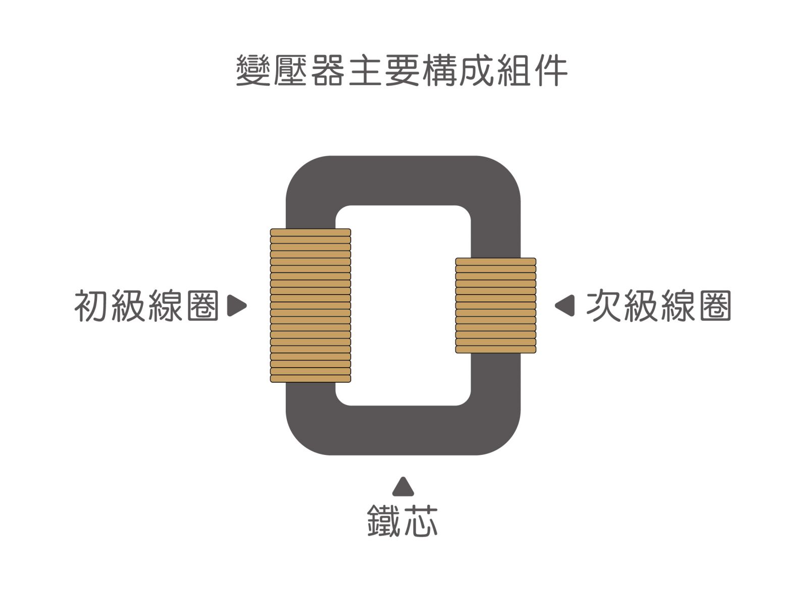
When there is an alternating current in the primary coil, an alternating magnetic flux is generated in the iron core (or magnetic core), so that the secondary coil induces a voltage (or current), which is used in the power supply as boost, buck, and isolation.
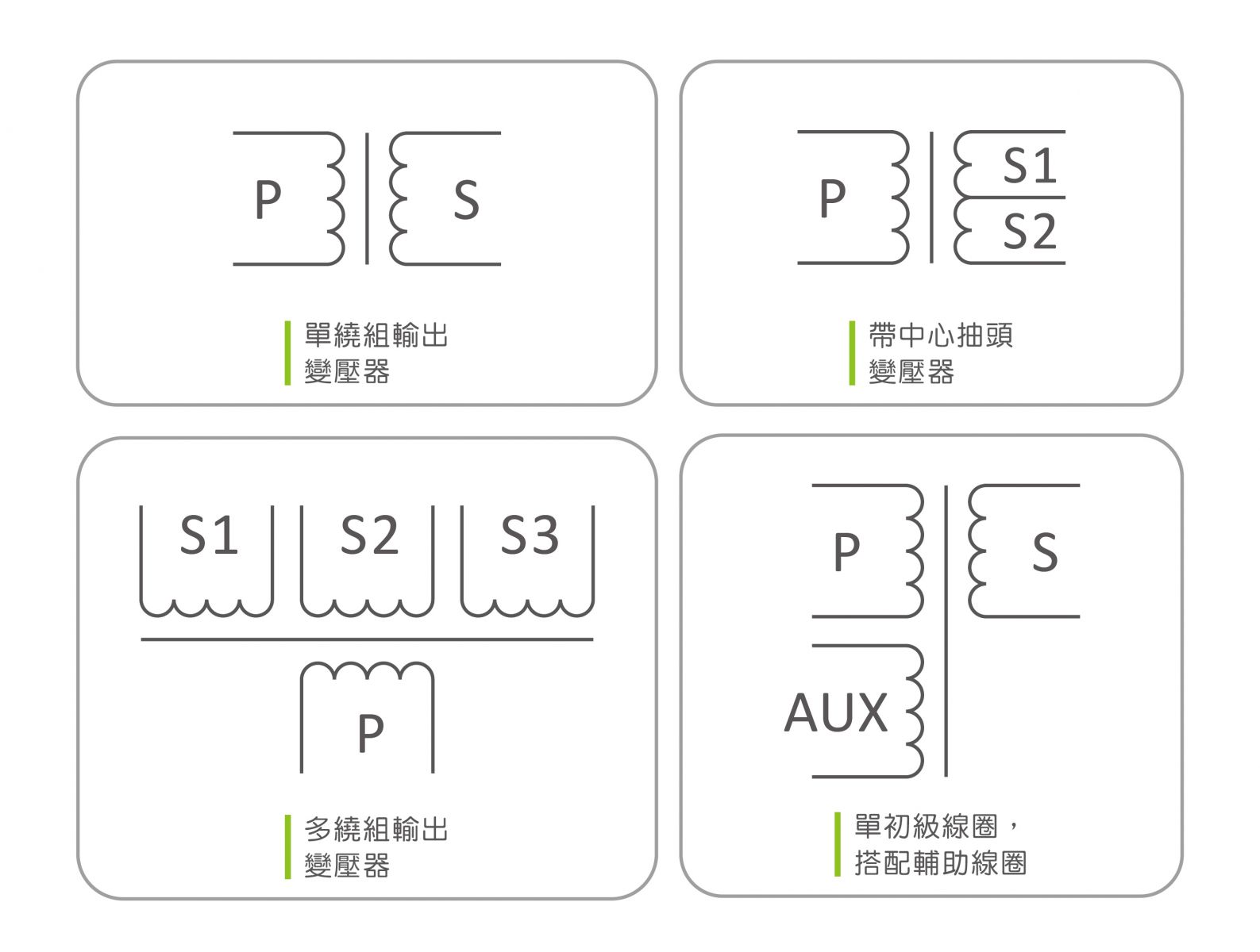
3. Symbols of transformers :
4. Advantages of high frequency transformers :
For high-frequency transformers used with DC buck-boost technology, the switching frequency is generally at least greater than 10KHz, and the maximum switching frequency is limited by the heat resistance of the switching power components (BJT, MOSFET, IGBT) and the iron loss of the core material. Size, in other words, everything is limited by the temperature that the material can endure. The core material of this type of transformer used in the power supply is changed to ferrite power material, which is generally referred to as a high-frequency transformer.
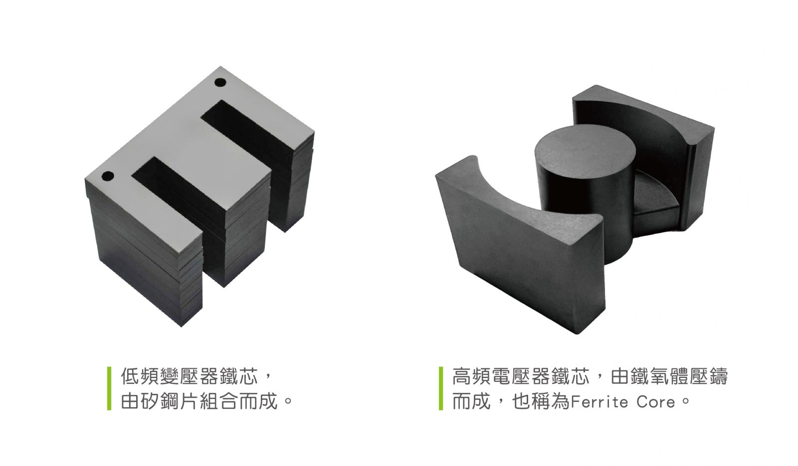
In the case of higher power consumption and longer transmission distances, AC power systems far outperform DC systems. Generally speaking, the AC power system is either 50Hz or 60Hz. As long as it is a transformer designed for the power frequency of 50Hz/60Hz, it is generally called a "low frequency transformer". It is generally used in conjunction with the power system, also called a power transformer. The core material is mainly silicon steel sheet.
The frequency is determined by the switching times of the switching element per second, so it is also called the switching frequency fs. When the input voltage of the transformer is the same, increasing the switching frequency can reduce the number of turns N, and reduce the size of the iron core, and how much power to transmit determines the wire. Wire diameter, so usually raising the switching frequency is to reduce the number of turns or downsize the the iron core, so the volume of the high-frequency transformer will be much smaller than the volume of the low-frequency transformer.
5. Design principle of high frequency transformer
• Leakage inductance, in the design of high-frequency transformers, the leakage inductance of the transformer is caused by the incomplete coupling of the magnetic flux between the primary coil and the secondary coil, and the magnetic lines of force generated by the coil cannot all pass through the secondary coil. The leakage inductance is called leakage inductance; the designer, the wider the window, the smaller the number of turns, the less the number of stacked layers, the lower the leakage inductance, or the primary and secondary stacks are offset to reduce the generation of leakage inductance. This is called sandwich winding method.• Distributed capacitance, between the turns of the transformer winding, between the upper and lower layers of the same winding, or between different windings, the capacitance formed between the winding and the mask layer is called distributed capacitance; designers usually place the primary winding on the innermost layer, so that the length of each turn of the primary winding of the transformer can be the shortest, and this effectively reduces the distributed capacitance of the primary winding itself, but the sandwich winding method will increase the parasitic capacitance and reduce the efficiency, so this is also a designer need to be considered.
• Because the high-frequency transformer in the switching power supply transmits a high-frequency pulse square wave signal. During the transient process of transmission, leakage inductance and distributed capacitance will cause inrush current and peak voltage, oscillating at the top, resulting in increased loss, which is the main reason why low leakage inductance is required in the design. On the contrary, there are also designers use leakage inductance for detection, because different designers have different requirements and design methods.
• Insulation Tape, it is usually necessary to add (2-3) layers of insulating tape between the primary winding and the secondary winding, which can reduce the capacitance of the distributed capacitance between the primary winding and the secondary winding, and also increase the isolation strength of primary and secondary windings. The dielectric strength between the classes ensures the dielectric withstand voltage requirements. Usually 1-2 layers for 1000V AC tape, 2-3 layers for 3000V AC tape.
• The shielding process is to more effectively solve the interference problem of the transformer. Conductive copper foil is added between the windings or the outermost layer of the iron core, but it must be noted that the conductive copper foil used between the windings is also grounded, which will increase the thermal resistance. Generally, the conductive copper foil will be grounded on the outermost layer of the iron core or wire package. Or you can add insulating tape to the outermost layer of the iron core to increase the shielding effect.
• Insulation and withstand voltage are the keys to the design of high frequency transformers. When the withstand resistance conditions are severe, or the safety distance of the wire frame design is not enough, the resistance specification of the material can be increased, or the use of retaining walls, tapes, tubes, Impregnation and other processes to increase the withstand voltage between the primary and secondary or safety distance, or use sleeve to ensure safety distance between tinning or wire wrap is a common way.
Related articles :
• APPLE MagSafe tangle dancing with Qi2 MPP
• What is copper loss? What is the skin effect ? The difference between Isat and Irms
• What is an inductor?