What is an inductor? What is the definition of an inductor? Overview of inductor characteristics, parameters, and types.
![]() 2023.2.10
2023.2.10
 Articles
 Articles
1. What is an inductor ?
Passive components inductor refer to electronic components that cannot generate power on their own, making them essential for supporting roles in electronic circuits.
2. Definition of inductance
An inductor is the ratio of the magnetic flux of a wire to the current that produces in and around the wire when an alternating current passes through the wire, and the magnetic flux of the wire is the ratio of the current that produces this flux.
When a DC current passes through the inductor, only fixed magnetic field lines appear around it, which do not change with time; However, when an AC current passes through the coil, it will be surrounded by magnetic field lines that change over time. According to Faradhi's law of electromagnetic induction- the analysis of magnetoelectric electricity, the changing magnetic field lines will produce an inductive potential at both ends of the coil, which is equivalent to a "new power supply".
When a closed loop is formed, this induced potential generates an induced current. The total amount of magnetic field lines generated by the induced current is known by The Law of The Rings is intended to prevent the original changes in the magnetic field lines. Since the original magnetic field line change is derived from the change of the applied alternating power supply, from the objective effect, the inductive coil has the characteristic of preventing the current change in the AC circuit.
Inductor coil has similar characteristics to inertia in mechanics, electrically named "self-induction", usually in the opening of the gate switch or on the brake switch at the moment, a spark will occur, which is the phenomenon of self-inductance caused by a high inductive potential.
➤ In short, when the inductor coil is connected to the AC power supply, the magnetic field lines inside the coil will change with the alternating current, resulting in electromagnetic induction in the coil. This electromotive force, which is generated by changes in the current of the coil itself, is called "self-induced electromotive force". It can be seen that the inductance is only a parameter related to the number of coils, the size and shape and the medium, which is a measure of the inertia of the inductor coil and has nothing to do with the applied current.
3. The main characteristics and parameters of the inductor
3.1 Inductance (L)
The inductance L represents the inherent characteristics of the coil itself, independent of the current size. In addition to the special inductance coil (color code inductor), the inductance value is generally not specifically marked on the coil, but marked with a specific name.
3.2 Inductive reactance (XL)
The size of the inductor coil's obstruction effect on the AC current is called the Inductive reactance-XL, and the unit is Ohm. Its relationship with the inductance L and the AC frequency f is XL=2πfL
3.3 Quality Factor (Q)
The quality factor Q is a physical quantity that represents the mass of the coil, and Q is the ratio of the inductive impedance XL to its equivalent resistance, i.e., Q = X L / R.
The higher the Q value of the coil, the smaller the loss of the loop. The Q value of the coil is related to factors such as the DC resistance of the wire, the dielectric loss of the skeleton, the loss caused by the shield or core, the effect of the high-frequency skin effect, and so on. The Q value of the coil is usually tens to hundreds. Using a core coil, multiple strands of coil can increase the Q value of the coil.
3.4 DC Resistance (DCR)
The inductor coil measures the resistance at non-alternating current, in the inductor design, the smaller the DC resistance, the better, and its measurement unit is Ohm, usually marked by its maximum value.
3.5 Distributed Capacitance
The capacitance present between the turns and turns of the coil, between the coil and the shielding cover, and between the coil and the bottom plate is called the distributed capacitor. The presence of distributed capacitance reduces the Q value of the coil and makes the stability worse, so the smaller the distributed capacitance of the coil, the better. The use of segmented winding reduces the distributed capacitance.
3.6 Impedance value
The impedance value of the inductor refers to the sum (complex number) of all its impedances under the current, including the AC and DC parts, the impedance value of the DC part is only the DC resistance (real part) of the winding, and the impedance value of the AC part includes the reactance (imaginary part) of the inductor. In this sense, inductors can also be thought of as "AC resistors".
3.7 Rated current
Allowing the continuous DC current intensity of an inductor, the intensity of this DC current is based on the maximum temperature rise of the inductor at the maximum rated ambient temperature, the rated current is related to the ability of an inductor to reduce the loss of the winding by a low DC resistance, and is also related to the ability of the inductor to disperse the energy loss of the winding, therefore, the rated current may be increased by reducing the DC resistance or increasing the inductor size to increase the current waveform of the low frequency. The RMS current value can be used in place of the DC rated current, which is not related to the magnetism of the inductor.
4. Types of Inductors
According to the inductance form classification : fixed inductor, variable inductor.
Classified according to the nature of the conductive magnet : air core coil, ferrite coil, iron core coil, copper core coil.
According to the nature of work : antenna coil, oscillation coil, choke coil, notch coil, deflection coil.
Classification by winding architecture : single-layer coil, multi-layer coil, hive coil.
According to the operating frequency classification : high frequency coil, low frequency coil.
Classified according to architecture characteristics : core coil, variable inductance coil, color code inductance coil, non-core wire
➤ Classification by inductive process :
| Classification by inductive process | (1) Chip winding inductor | (2) Chip type high-frequency inductor | (3) Multilayer inductors |
|---|---|---|---|
| Product picture | 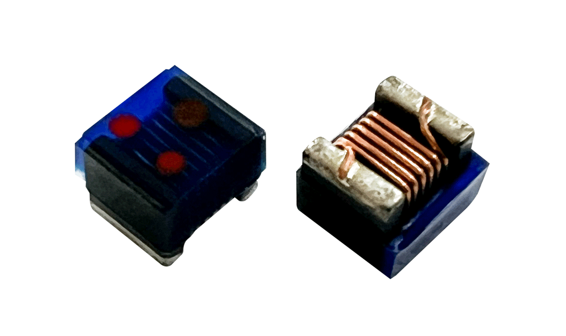 |
 |
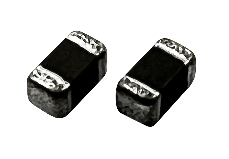 |
| Series | GNLC , GNLT | GTH | GBL , GBLH |
| Size | 1610 , 2012 , 2520 , 3225 and more sizes. | 1005 , 1608 , 2012 , 2520 | 100505 , 160808 , 201209 , 321611 and more sizes. |
| Inductance | 120 nH~1mH | 100 nH ~ 10mH | 47 nH ~ 47 uH |
| Rated Current | 50 mA ~ 3.0 A | 5 mA ~ 8.0 A | 1 mA ~ 4.0 A |
| DC Resistance | 0.06 Ohm ~ 46.0 Ohm | 0.006 Ohm ~ 2.0 Ohm | 0.060 Ohm ~ 5.0 Ohm |
| Material | Ferrite | Ceramic | Ferrite volumetric ceramic / ferrite layered |
| Inductor tolerance accuracy | J=±5% , K=±10% | D=±0.1nH , S=±0.3nH , G=±2% , J=±5% | J=±5% , K=±10% , M=±20% , N=±25% |
| Example | 1610=1.80mm*1.20mm*1.00mm 2012=2.40mm*1.65mm*1.25mm |
1005=1.0mm*0.5mm*0.5mm 2012=2.0mm*1.2mm*0.9mm |
/ |
| Description | Winding type, small size, high production capacity, low cost. | • There are two kinds of winding type / multilayer type, winding type, product automatic winding, the surface is semi-wrapped with UV glue to the coil. • The multilayer type adopts micron-level sheet printing conductor pattern and hole stacking, laminated assembly and forming, and the two kinds of structure have the characteristics of small size, high production capacity and low cost, which are suitable for high-frequency product applications. |
• Multilayer chip beads use ferrite design and multilayer process, the impedance value changes with frequency, high impedance is achieved at high frequency, there is better high frequency filtering, and EMI noise interference can be effectively suppressed. • Chip beads are transmission lines connected in series with noise radiation sources, very convenient and effective noise elimination components, can be widely used in various devices, such as mobile phones, tablets, notebooks, motherboards, power supply, charger, monitors, TV , network routers. |
| Classification by inductive process | (4) Multilayer EMI Ferrite Bead | (5) Color Code Inductor | (6) Molding inductor/Choke |
|---|---|---|---|
| Product picture | 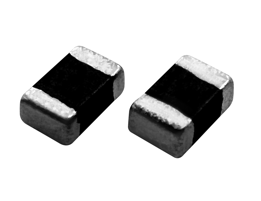 |
 |
 |
| Series | GBD | GAL | GSTC , GSTD , GSTM , GSTL GSFH , GSFM , GSNH |
| Size | 060303 , 100505 , 160808 , 201209 321611 , 322513 , 453215 |
0204 , 0307 , 0410 , 0512 | 1608 , 2012 , 3012 , 3020 , 4020 , 5030 6030 , 1040 , 1265 , 1770 , 2320 and more sizes. |
| Inductance | Impedance : 6 Ohm ~ 3000 Ohm | 0.1 uH ~ 33 mH | 0.1 uH ~ 300 uH |
| Rated Current | 5 mA ~ 8.0 A | 20 mA ~ 2.0 A | 1 A ~ 120 A |
| DC Resistance | 0.006 Ohm ~ 2.0 Ohm | 0.03 Ohm ~ 250 Ohm | 0.0001 Ohm ~ 0.5 Ohm |
| Material | ferrite multilayer | / | / |
| Inductor tolerance accuracy | M=±20% , N=±25% | J=±5% , K=±10% , M=±20% | |
| Description | • Multilayer chip beads use ferrite design and multilayer process, the impedance value changes with frequency, high impedance is achieved at high frequency, there is better high frequency filtering, and EMI noise interference can be effectively suppressed. • Chip beads are transmission lines connected in series with noise radiation sources, very convenient and effective noise elimination components, can be widely used in various devices, such as mobile phones / tablets / notebooks / motherboards / power supply / charger / monitors / TV / network routers... etc. |
• The color code inductor is a color ring of four different colors on the surface of the inductor to express the inductor value and tolerance information. • Reading: Indication of the color code resistors. |
• Molding inductors are mainly small inductors that use metal powder to be molded . • Features: highly automated production, good saturation current performance. |
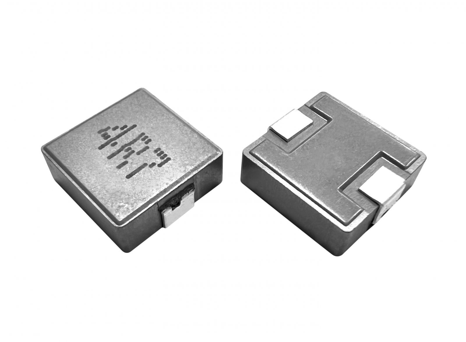
| Classification by inductive process | (7) Dip Axial Winding Inductor | (8)Toroidal Inductor | (9) Flat Wire High Current Inductor |
|---|---|---|---|
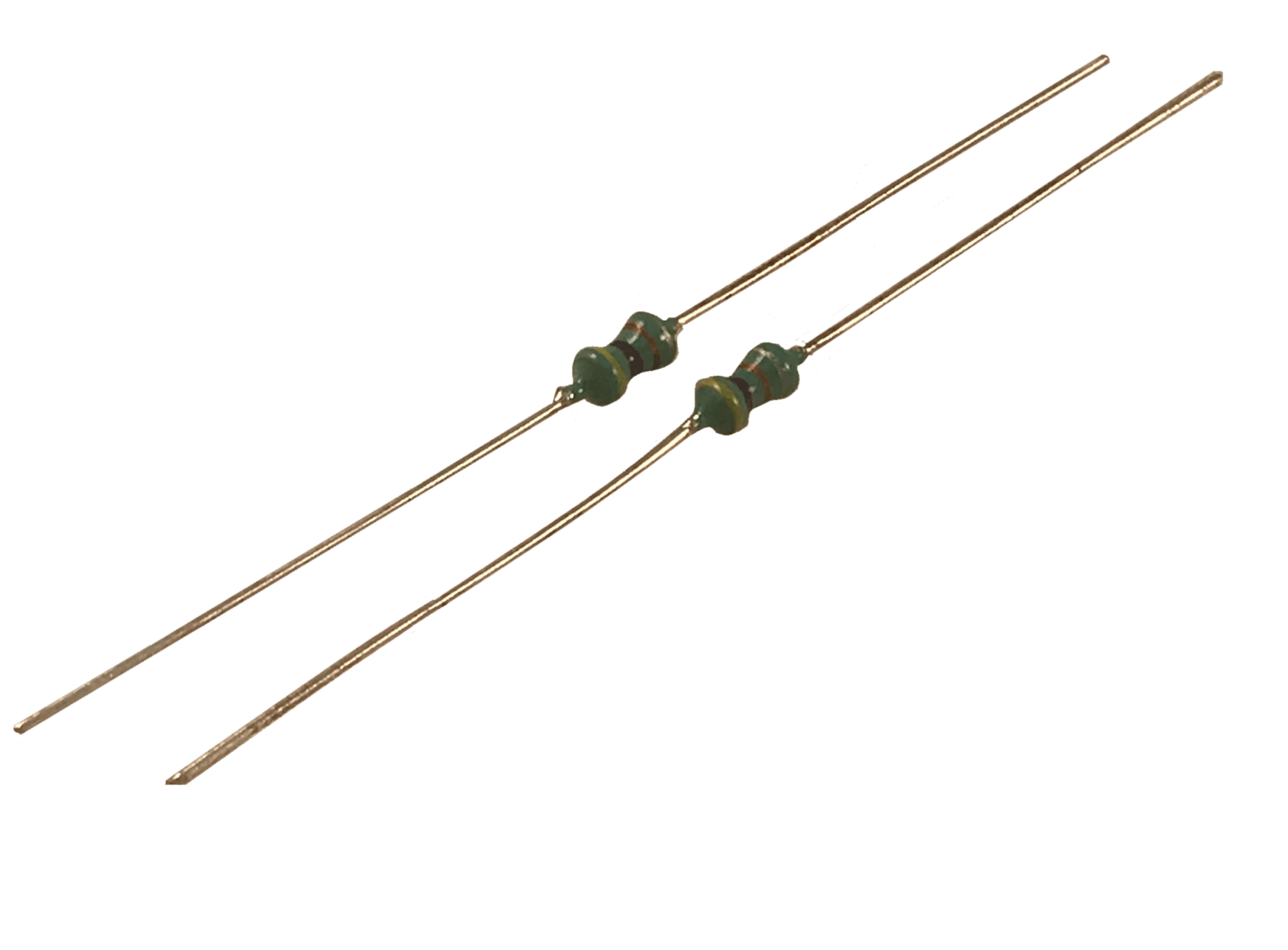
| Product picture |  |
 |
 |
| Series | GDR , GDRE | GCL , GTX | GSTF1050, GSTF1250, GSTF1265, GSTF2816, GSTF2818 |
| Size | 0406 , 0608 , 0810 , 1012 and more sizes. | Core : 2526 , 3026 , 3052 , 4452 5026 , 6018 , 8026 and more sizes. |
10 x 10 ~ 28 x 28 mm , and more sizes. |
| Inductance | 0.1 uH ~ 50 mH | 0.1 uH ~ 100 mH | 0.1 uH ~ 100 uH |
| Rated Current | 65 mA ~ 10.0 A | 0.01 A ~ 50.0 A | 1 A ~ 80 (A) |
| DC Resistance | 0.0001 Ohm ~100.0 Ohm | 0.0001 Ohm ~ 100.0 Ohm | 2.0 m Ohm ~ 20 m Ohm |
| Description | • Traditional drum choke inductor, the Q value is high, the price level is generally low, and the self-resonance frequency is high. | • It can be wire wound by various iron powder cores or ferrite magnets, with low to high inductance, small loss and wide application. | • The use of flat wire coil with high power iron EE/EI core, with low loss, high current and other characteristics. |
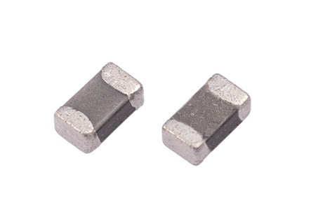
| Classification by inductive process | (10) SMT Type Assembly Inductor | (11) Multilayer High-Frequency Inductor | |
|---|---|---|---|
| Product picture | 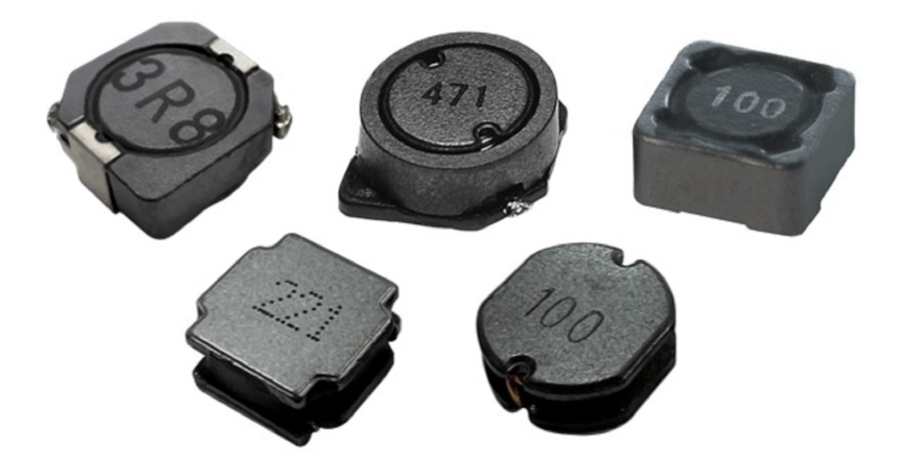 |
 |
|
| Series | GNR , GSDRH , GSDRK GSSR2 , GTV , GSTF |
GTC | |
| Size | 2.5x2.5, 3x3, 4x4, 5x5, 6x6, 7x7, 8x8, 10x10, with various Height , and more sizes. | 1005 , 1608 , 2012 | |
| Inductance | 0.80 uH ~ 10000 uH | 0.60 nH ~ 500 nH | |
| Rated Current | 0.01 A ~ 50.0 A | 80 mA ~ 850 mA | |
| DC Resistance | 0.00029 Ohm ~ 220.0 Ohm | 0.10 Ohm ~1.90 Ohm | |
| Description | • Assembled inductor is an inductor processed by assembly using enameled wire and ferrite materials, which has the advantages of full size, wide range of specifications, etc., but because most of the automation isn't high, the cost is high. | • Multilayer High-Frequency Inductor is an inductor made of vacuum thin film process, high reliability, easy to integrate and chip type, very suitable for automated surface mount technology (SMT), with its small size, good in high frequency characteristics and other advantages. | |
➤ Check the product database to find the inductor you need.
Related articles:
• Notes on the use of 【 inductor coils 】
• APPLE MagSafe tangle dancing with Qi2 MPP
• What is copper loss? What is the skin effect ? The difference between Isat and Irms
If you are interested in our products, please Contact Us.