What is the Q value of the inductor? How do I increase the Q value?
![]() 2022.7.6
2022.7.6
 Articles
 GOTREND Technology Co.,Ltd
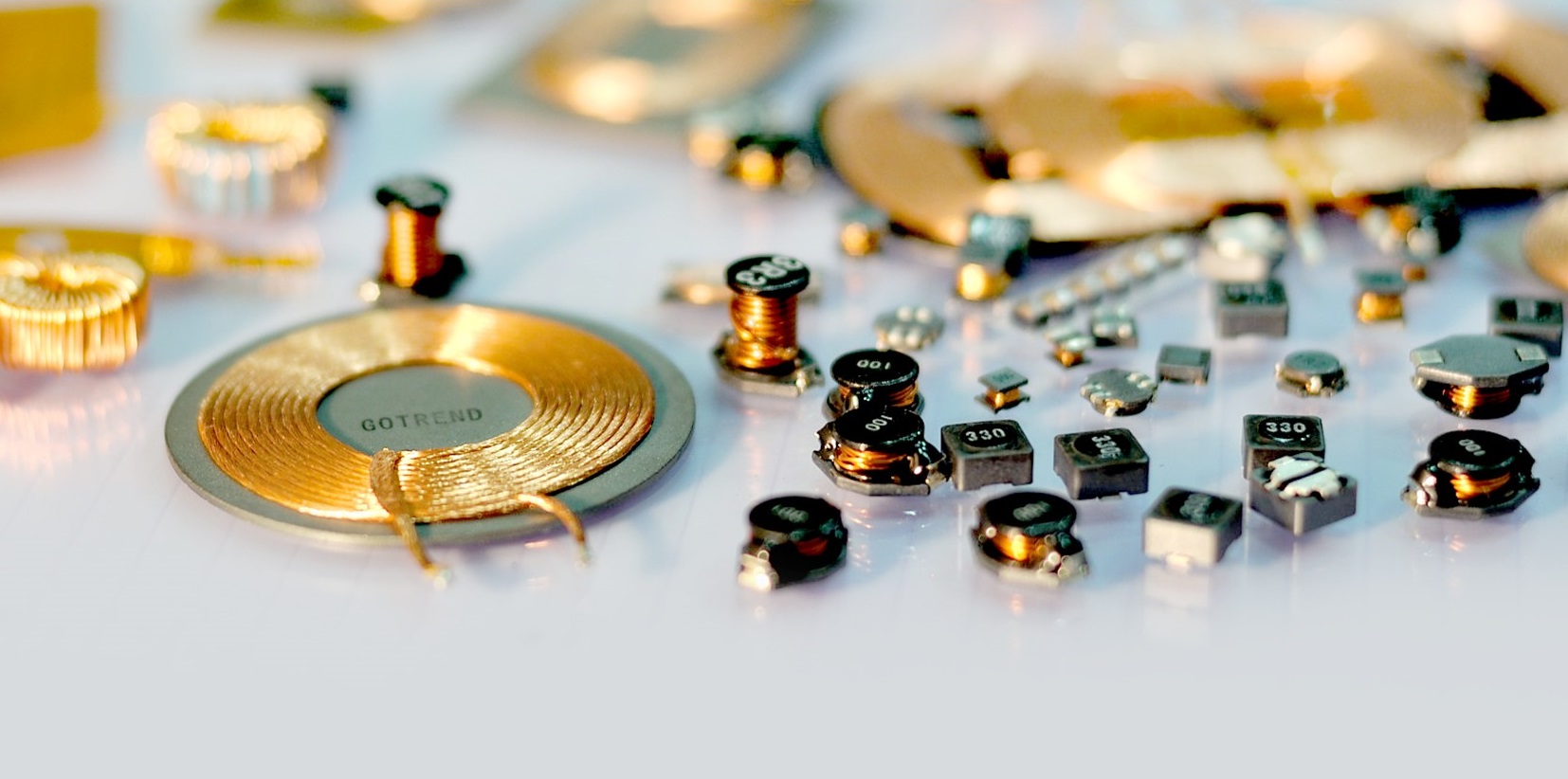
Passive component inductors in all kinds of circuit applications are very common, but the classification is also very rich, according to different properties, forms or structures, can be divided into a variety of types, as for the inductor coil Q value how to define? It is stated that the higher its Q value, specifically a higher Q factor, the better. So, how can this Q factor be increased?
First of all, let's recognize the Q value, what is the Q value?
1、Definitions Inductor Q value :
Also known as the quality factor of the inductor, it is the main parameter to measure the inductor device. Refers to the inductor when operating at an AC voltage at a certain frequency. The ratio of its equivalent loss resistance. The higher the Q value of the inductor, the smaller its loss and the higher the efficiency.
2、Formula for Q value :
The mass factor can also be written as the energy stored in the Q=2pi* circuit / the energy consumed by the circuit in a cycle. The relationship between the passband BW and the resonant frequency w0 and the mass factor Q is: BW = wo/Q, indicating that if Q is large, the passband bandwidth is narrow, and if Q is small, the passband bandwidth is small.
Q= WL/R = 1/gwl [1]
Thereinto:
• W is the power supply frequency when the circuit is resonant
• L is an inductor
• R is the cascading resistor
• G is the conductance
• Q value is the quality factor, it is the ratio of active power to total active power
3、Definition of inductor quality factor Q :
Q value is to take into account the basic parameters of the inductor, that is, refers to the inductor in a certain frequency of the AC circuit, the impedance angle caused by the ratio of its equivalent series circuit wear resistance value, the higher the Q value of the inductor, the smaller the loss, and the higher the efficiency. Quality factor Q is an important parameter that reflects the quality of the coil, and improving the Q value of the coil can be called one of the key points to be paid attention to in the winding coil
So, how to improve the Q value of the inductor, the following explains the specific way :
1、 Inductor coils working in the low frequency band are generally wound from transmission lines with insulated sleeves such as wire-clad wires.
Inductor coil output power is higher than tens of thousands of Hz, and less than 2MHz lines, the transmission line winding coil using multi-core insulated wires, in that way, the surface area of the conductor can be reasonably increased, and then the harm of skin effect can be handled, so that the Q value can be 30%-50% higher than the coil wound of a transmission line of the same cross-section. In lines with frequencies higher than 2MHz, the inductor coil should be wound using a thick transmission line, and the aperture of the transmission line is generally 0.3mm-1.5mm. An interwound inductor coil is wound using an electroplated copper core wire to improve the conductivity of the surface layer of the transmission line. When the inductor coil is not suitable for multi-core transmission line winding, because the multi-core insulated cable in the frequency is very high, the coil insulation sleeve compound will cause additional loss, its effect is not as good as a single transmission line.
2、The use of high-quality coil skeleton(Bobbin), reduce the loss of organic chemicals :
In places with high frequencies application, such as short-wave bands, due to the general coil structure, the loss of organic chemicals is significantly improved, therefore, high-frequency compound raw materials, such as high-frequency ceramic, high-density PTFE relatively high density, high hardness of high-density polyethylene, etc. should be taken as a framework, and the interwinding method should be used.
3、Select valid coil model specifications :
It can reduce the loss of a certain outer diameter of a single-sided coil (φ20mm-30mm), when the winding resistance length L and diameter D market share L/D = 0.7 when it has minimal loss; Multilayer coils with a certain diameter L/D = 0.2-0.5, with t / D = 0.25-0.1, its loss is the lowest.
Winding resistance of it’s thickness and thinness t winding . In the case of a short resistance L and a diameter D that guarantee 3t + 2L = D, the loss is also minimal. The coil with anti-interference ability magnetic core is best when its L/D = 0.8-1.2.
4、Select the diameter of the core with effective anti-interference ability :
The use of a shielding will increase the loss of the coil, so that the Q value is reduced, so the model specification of the shielding cannot be too small. If the shield is too large, the volume will be expanded, so select the diameter model specification of the effective shield. When the ratio of the shielding cover diameter Ds to the coil diameter D is ensured as shown below, that is, Ds/D = 1.6-2.5, the Q value is reduced by no more than 10%.
5、The use of magnetic core can make the number of coil turns significantly reduced, the use of magnetic cores in the coil, reducing the number of coil turns, not only reduce the resistance of the coil, conducive to the increase of Q value, and reduce the volume of the coil.
6、Select the large coil diameter moderately:
Conducive to reducing loss under the possible conditions, the diameter of the coil is selected to be larger, and the volume is expanded, which is conducive to reducing the loss of the coil. General use of reception, single-sided coil diameter to take 12mm-30mm ; Double-layer coils take 6mm-13mm, but it is not suitable for the category of higher than 20mm-25mm.
7、Reduce the distributed capacitance of the winding coil :
As far as possible, choose the unstructured method to wind the coil, or wind the coil on the convex rib structure, which can reduce the distributed capacitance by 15%-20%; The segment winding method can reduce the distributed capacitance of multilayer coils by 1/3 to 1/2.
For double-layer coils, the smaller the diameter D, the longer the winding resistance L . The smaller or the larger the winding resistance, the smaller the distributed capacitance. It should be taken very seriously: after the coil has been varnished and coated, its distribution electricity Capacity will be expanded by 20%-30%. Overall, winding, from beginning to end, to increase the Q value, reduce losses, as the key to consideration.
Related articles :
• APPLE MagSafe tangle dancing with Qi2 MPP
• What is copper loss? What is the skin effect ? The difference between Isat and Irms
• What is an inductor?