Technical application note for common mode choke
![]() 2022.12.20
2022.12.20
 Articles
 GOTREND Technology Co.,Ltd
Content
1. Introduction to common mode Inductors
2. Common mode & differential mode interference
3. The main source of differential mode noise and common mode noise
4. How common-mode inductors suppress common-mode noise
5. Common mode inductor selection
6. Summary
1.Introduction to common mode Inductors
Common Mode Choke (Common Mode Filter ) , also known as common mode inductors, are coils with the same number of turns symmetrically wound in opposite directions on a closed magnetic ring. Commonly used to filter common-mode electromagnetic interference, suppress the electromagnetic waves generated by high-speed signal lines to radiate outwards, improve the EMC (=EMI+EMS) of the system, and generally add common-mode inductance on differential signal lines in practical applications.
2. Common mode & differential mode interference
To understand the application of common mode inductors, you need to understand what is common mode interference and differential mode interference.
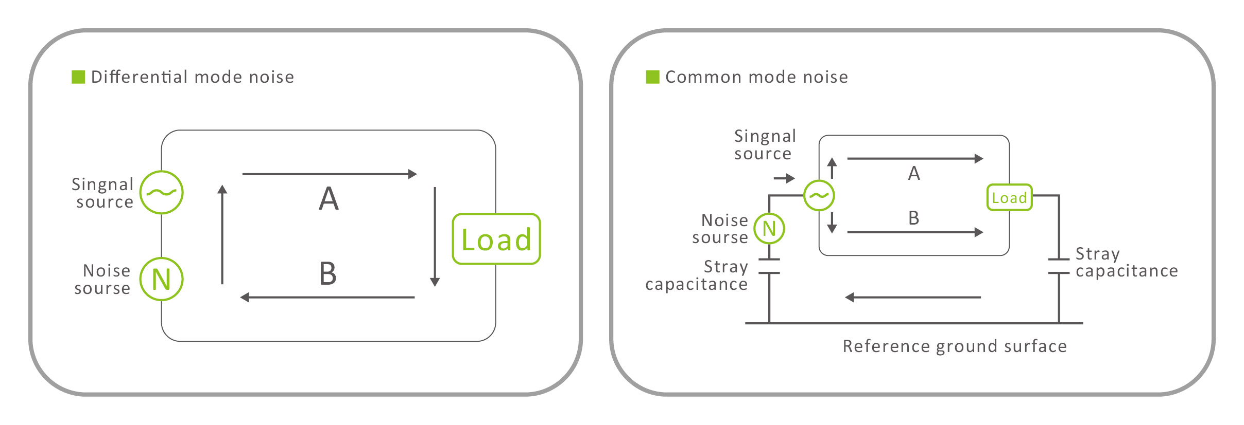
Common mode and differential mode are both relative quantities, common mode refers to the potential of two signals A and B relative to the reference point (GND) ; Differential mode refers to the relative value between A and B.
Common-mode interference refers to the interference of two signal lines to the ground, if the environment produces the same directional and equal-amplitude interference (superimposed on the same voltage) between the two signal lines to the ground, then it is called common-mode interference, the reason why the differential signal has good common-mode suppression, because the differential amplifier only amplifies the difference between the two signals, if it is a common-mode interference of equal size, it can be completely eliminated, (Udiff=Ua-Ub) differential mode interference refers to the serial mode, Refers to the difference between two signal lines, the differential mode interference is equivalent to adding an interference voltage between the two signals, Unoise = Ua-Ub.
As shown in the following figure :
1. Introduction to common mode Inductors
2. Common mode & differential mode interference
3. The main source of differential mode noise and common mode noise
4. How common-mode inductors suppress common-mode noise
5. Common mode inductor selection
6. Summary
1.Introduction to common mode Inductors
Common Mode Choke (Common Mode Filter ) , also known as common mode inductors, are coils with the same number of turns symmetrically wound in opposite directions on a closed magnetic ring. Commonly used to filter common-mode electromagnetic interference, suppress the electromagnetic waves generated by high-speed signal lines to radiate outwards, improve the EMC (=EMI+EMS) of the system, and generally add common-mode inductance on differential signal lines in practical applications.
2. Common mode & differential mode interference
To understand the application of common mode inductors, you need to understand what is common mode interference and differential mode interference.
Common mode and differential mode are both relative quantities, common mode refers to the potential of two signals A and B relative to the reference point (GND) ; Differential mode refers to the relative value between A and B.
Common-mode interference refers to the interference of two signal lines to the ground, if the environment produces the same directional and equal-amplitude interference (superimposed on the same voltage) between the two signal lines to the ground, then it is called common-mode interference, the reason why the differential signal has good common-mode suppression, because the differential amplifier only amplifies the difference between the two signals, if it is a common-mode interference of equal size, it can be completely eliminated, (Udiff=Ua-Ub) differential mode interference refers to the serial mode, Refers to the difference between two signal lines, the differential mode interference is equivalent to adding an interference voltage between the two signals, Unoise = Ua-Ub.
As shown in the following figure :
Two signals with equal amplitude phase opposites, oscillating with a common-mode voltage as the reference, are called differential signals. If one end is grounded, it becomes a single-ended signal. If the common mode voltage of A and B signals is 1.2V (LVDS), then A and B are 350mV differential mode on 1.2V, and the high and low levels are determined by their differences, so they can well suppress common mode interference, as long as the zero point of the two signals can control the logic state of the signal, compared with the single-ended threshold level relative to ground, it has the advantages of strong resistance to common-mode interference, suitable for voltage transmission, and less EMI.
The reason why a common-mode choke is needed for differential signals is because differential amplifiers have a common-mode rejection ratio that distorts beyond this CMRR.
The following figure is a concrete implementation diagram of differential (LVDS) :
The reason why a common-mode choke is needed for differential signals is because differential amplifiers have a common-mode rejection ratio that distorts beyond this CMRR.
The following figure is a concrete implementation diagram of differential (LVDS) :
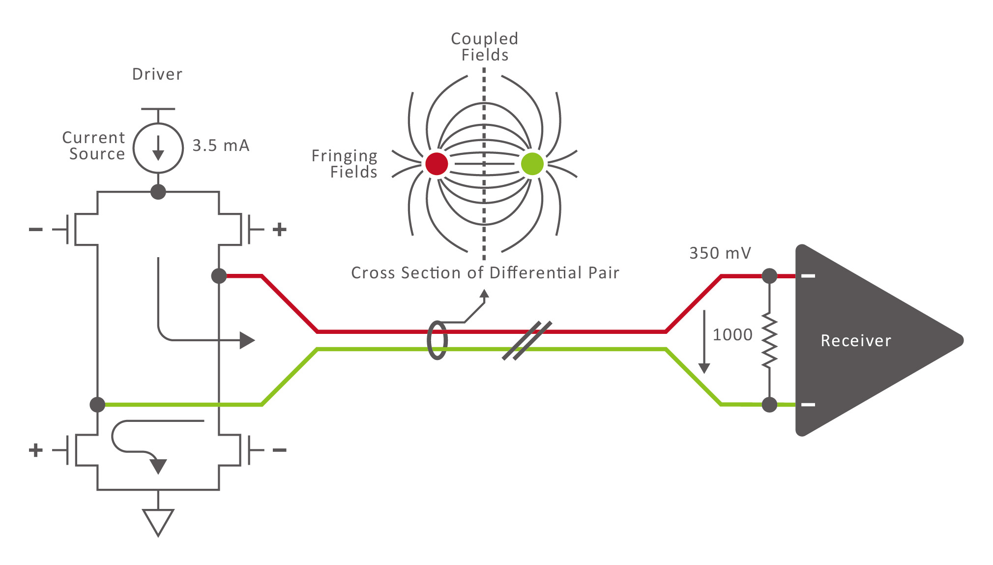
As can be seen from the above figure, due to the coupling of differential signals to each other, the external EMI is also relatively small.
Common-mode inductance suppresses common-mode interference :
According to the right-hand screw rule, when two coils in the opposite direction of the same magnetic circle pass through two voltages with the same polarity and equal amplitude, the resulting magnetic flux is superimposed on each other, and the inductive reactance is: Xl= wL, and the inductive reaction is very large. The magnetic flux generated by differential signals cancels each other out.
Loops for differential signals :
When the local reference plane is discontinuous, the two signals can provide a loop, but the coupling strength of the ground is still large, and the ground is generally used as the loop.
3. The main source of differential mode noise and common mode noise
For switching power supplies, if the energy storage filter large capacitance behind the rectifier bridge is the ideal capacitance, that is the equivalent series resistance is zero (ignoring all capacitance parasitic parameters), all possible differential mode noise sources input to the power supply will be completely bypassed or decoupled by the capacitor, but the equivalent series resistance of the bulk capacitor is not zero. Therefore, the equivalent series resistance of the input capacitor is the main part of the impedance Zdm that is seen from the differential mode noise generator.
In addition to the input capacitor to withstand the operating current flowing from the power line, it also provides the high-frequency pulse current required by the switch tube, but in any case, the current flowing through the resistor will inevitably produce a voltage drop, such as the equivalent series resistance of the capacitor, so there will be high-frequency voltage ripple at both ends of the input filter capacitor, and the high-frequency high-voltage ripple is from the differential mode current. It is basically a voltage source (caused by an equivalent series resistor).
Theoretically, when the rectifier bridge is on, this high-frequency ripple noise should only appear on the input side of the rectifier bridge, in fact, when the rectifier bridge is turned off, the noise will leak through the parasitic capacitance of the rectifier bridge diode.
There are many accidental paths for high-frequency currents to flow into the enclosure.
When the drain of the main switch in a switching power supply jumps, current flows through the parasitic capacitance between the switch and the heatsink (the heatsink is connected to the housing or the heatsink is the housing). When the AC grid current is maintained on by the rectifier bridge, the noise injected into the enclosure encounters almost equal impedance, so an equal amount flows into the zero line and the fire line. Therefore, this is pure common-mode noise.
4. How common-mode inductors suppress common-mode signals
It’s now known that the common-mode signal is two signals of equal amplitude and the same phase, the common-mode signal generally comes from the power grid, and the common-mode signal will affect the normal operation of the circuit board and interfere with the surrounding environment in the form of electromagnetic waves.
Since the inductor is used to suppress the common-mode signal, this must be related to the magnetic field.
First, let's introduce the energized spiral inductance and the direction of the magnetic field generated (For project applications, such as suppressing common-mode signals, there is less need for quantitative calculations, the magnetic field generated by the inductor, and the magnitude of the magnetic flux.) , the magnetic field generated by the inductor and the size of the magnetic flux. For the direction of the magnetic field of the energized solenoid, the method is to hold the solenoid in the right hand, and the four fingers point to the direction of the current, and the thumb point is the direction of the magnetic field.
Next, an important term is introduced, namely magnetic flux.
The total amount of magnetic field lines that pass vertically through a section is called the magnetic flux of that section, referred to as magnetic flux. Magnetic field lines are generated by energized solenoids, which actually exist, but can’t be seen or touched, magnetic field lines are a closed loop, for energized solenoids, magnetic field lines must pass through the inside of the solenoid, and the magnetic field lines are proportional to the magnetic induction strength B.
The magnetic flux is expressed in F, is a scalar, in Weber, codenamed Wb.
The relationship between magnetic flux and magnetic induction intensity B and cross-sectional area A is :
F = B A
From the relationship, we can see that the more lines of magnetic force pass through the cross section, the greater the magnetic flux. For a coil wound around a core, on which current i is passed, the inductance L of the coil can be expressed as :
L = N F / i
※ N is the number of coil turns.
Through the above brief overview, it can be understood that when the number of turns and current of the coil around the core are unchanged, the more magnetic field lines pass through the core, the greater the magnetic flux, and the corresponding inductance is also greater.
The role of the inductor is to prevent the change of the current flowing through it, and its essence is to prevent the change of its magnetic flux. This is the basic principle of using common-mode inductors to suppress common-mode currents.
How the common-mode inductor suppresses the common-mode current can be explained in one sentence, that is, when the common-mode inductor flows through the common-mode current, the magnetic flux in the magnetic ring is superimposed on each other, thereby having a considerable inductance and suppressing the common-mode current.
When two coils flow through the differential mode current, the magnetic field lines in the ferrite magnetic ring are opposite, resulting in magnetic flux canceling each other out, with almost no inductance, so the differential mode signal can pass through with basically no attenuation (considering that the inductor itself has a certain resistance).
Not only does the input filter of the switching power supply add a common-mode inductance, but also a common-mode inductor can be added to suppress the common-mode current when taking the differential signal line to prevent the circuit from triggering by mistake.
5. Common mode inductance selection
Depending on the rated current, DC resistance, and impedance value requirements of the common-mode inductor at the rated frequency, the design can be performed step by step:
(1) The minimum inductance value is calculated based on the impedance value
(2) Select the common mode inductive core material and core size
(3) Determine the number of coil turns
(4) Select the wire
Common mode inductance minimum inductance value calculation formula :
L = X1 / 2
※ Xl is the impedance value when the frequency is f.
The choke inductance value is the load (Units: Ohms) divided by the angular frequency or above at the beginning of the signal attenuation.
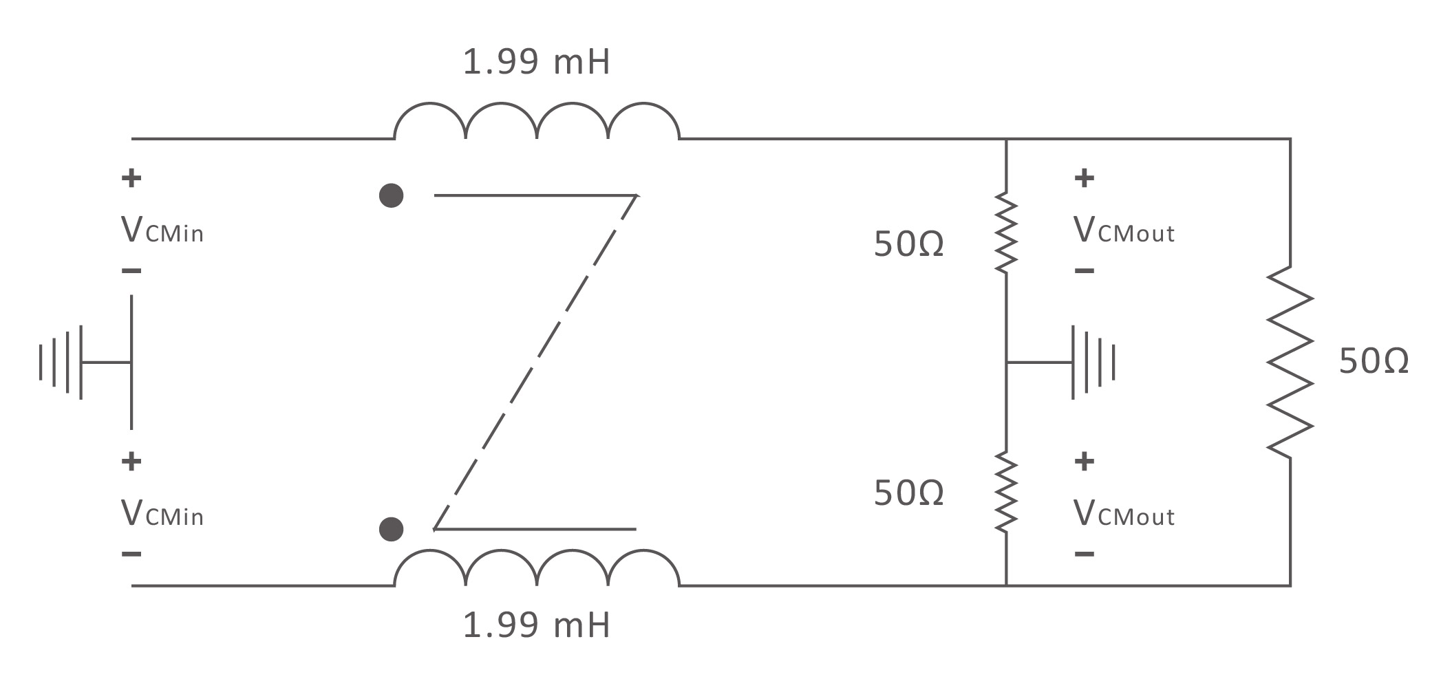
For example, in a 50Ω load, when the signal begins to attenuate at a frequency of 4000 Hz or more, an inductance of 1.99 mH (50/2π X 4000) is required.
Its corresponding common-mode filter construction is shown in the following figure :
The choke inductance value is the load (Units: Ohms) divided by the angular frequency or above at the beginning of the signal attenuation.
For example, in a 50Ω load, when the signal begins to attenuate at a frequency of 4000 Hz or more, an inductance of 1.99 mH (50/2π X 4000) is required.
Its corresponding common-mode filter construction is shown in the following figure :
Select the frequency band of the desired filter, the larger common-mode impedance, the better, so when selecting the common-mode inductor, you need to look at the device data, mainly according to the impedance frequency curve selection.
After the inductance is calculated, it’s the same as that of ordinary design inductors, and will not be described in detail here.
• Some things to pay attention to when winding the inductor :
(1) The wires wound on the coil core should be insulated from each other to ensure that no breakdown short circuit occurs between the turns of the coil under the action of instantaneous overvoltage.
(2) When the coil flows through the instantaneous large current, the core shouldn’t be saturated.
(3) The core in the coil should be insulated from the coil to prevent breakdown between the two under the action of instantaneous overvoltage.
(4) The coil should be wound as far as possible to a single layer, which can reduce the parasitic capacitance of the coil, enhance the coil's ability to give instantaneous overvoltage, when the common mode inductive core is selected, the shape size, applicable frequency band, temperature rise and price must be considered, and the commonly used core is U-shaped, E-type and ring-shaped.
6. Summary
Relatively speaking, ring cores are cheaper because rings only need one to make.
Other shapes of the core must have a pair to be used by common mode inductors, and in the molding, consider the pairing of the two cores, but also need to increase the grinding process to get a higher permeability, but for the ring core does not need this ; Compared with other shaped cores, the ring core has a higher effective permeability, because the two paired cores cannot eliminate the air gap phenomenon no matter how they are assembled, so the effective permeability is lower than that of a single closed core.
Ring core winding cost is higher, because other shape cores have a matching wire frame in use, winding can be machine operation, while ring core can only be manual work or machine (lower speed) operation ; And the magnetic ring aperture is small, the machine is difficult to thread, need to be manually wound, time-consuming and laborious, high processing costs, low efficiency ; Installation is inconvenient, if you add a base, the cost will rise.
Compared with the comprehensive performance, the magnetic ring performance is better and the price is relatively high.
Because of the cost factor, magnetic rings are mostly used in high-power power supplies. Of course, because of the small size, the volume of the small power supply, you can use a magnetic ring core. For common-mode inductors whose main function is to filter out low-frequency noise, a manganese-zinc ferrite core with high permeability should be selected; Instead, a nickel-zinc ferrite core or powder core suitable for high frequencies should be used.
It is usually suitable for high-frequency cores, because it has a distributed air gap, so the permeability is relatively low, and the two can’t be combined.
▶ However, unlike ordinary inductors, the role of common mode inductors is to form a large insertion loss to the noise signal to reduce noise interference.
Manganese zinc ferrite at high frequency, although its effective permeability is very small, but the core loss increases with the frequency increase, which has a greater hindering effect on high-frequency noise, so it can also weaken high-frequency interference, but the effect is relatively poor.
However, larger core losses cause the core to heat up, and cores with smaller losses are also more expensive.
Related articles :
• APPLE MagSafe tangle dancing with Qi2 MPP
• What is copper loss? What is the skin effect ? The difference between Isat and Irms
• What is an inductor?