In-depth Analysis of Inductor Voltage Endurance
![]() 2024.5.22
2024.5.22
 Articles
1、 Do inductors have voltage ratings?
Traditional wire-wound inductors and magnetic-sealed glue structure inductors use ferrite (insulator) as core material, with insulation resistance generally above 1KV. Hence, these inductors have relatively high voltage withstand values, which naturally meet typical voltage requirements in regular usage environments, ranging from a few volts to a dozen volts.
However, the construction of molded inductors differs, leading to lower voltage ratings that need consideration. The rated voltage of molded inductors is related to the iron powder used. Molded iron powder is coated with a thin layer of epoxy resin insulation. This thin insulation layer makes the molded inductor susceptible to breakdown due to insufficient voltage resistance of the iron powder when subjected to high voltages at both ends.
The thickness of the insulation layer varies due to differences among iron powder suppliers, and the molding pressure can also damage parts of the insulation layer. Therefore, molded inductors require a defined rated voltage operating value. In practical applications, such as in DC-DC boost or buck converters with significant voltage differentials, exceeding the rated voltage should be avoided.
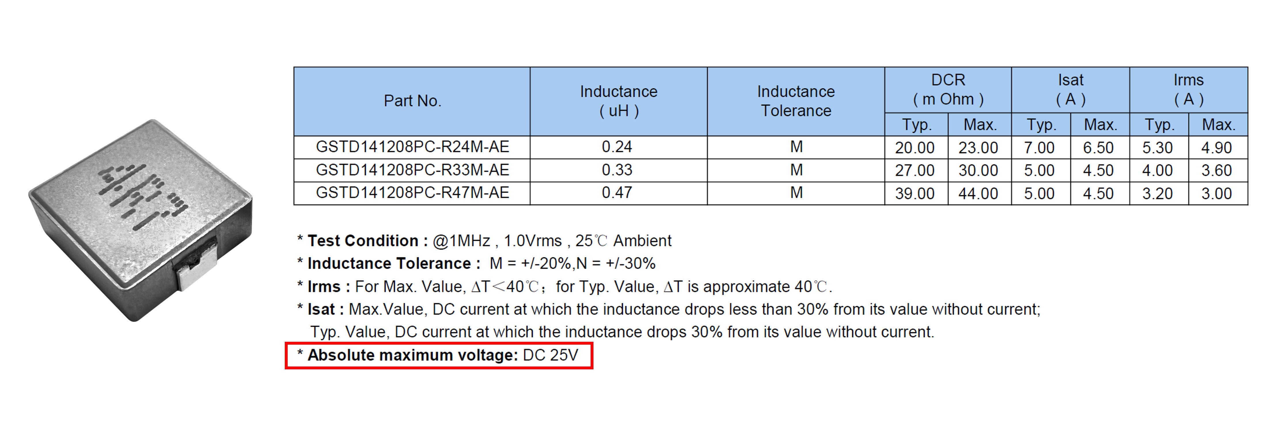
Fig. 1 GOTREND Molded inductors rated voltage
2、 Why is there no rated voltage specified on the datasheet for inductors?
While many electronic components, including capacitors, resistors, and integrated circuits, have specified rated voltages, inductors often do not.
This absence is due to the challenges associated with determining a rated voltage for inductors, either through testing or calculation. Additionally, inductors typically do not support DC or low-frequency operating voltages unless they have high inductance values (usually > 1 mH).
Validating the operating voltage through testing can be challenging and needs to be tailored to the specific application. Moreover, different manufacturing methods and process stresses, such as wire bending in the case of inductors, can render theoretical rated voltage calculations impractical.
3、 The Significance of Defining Rated Voltage for Inductor Components
Inductor components in DC applications of electronic products typically operate at voltages below 100V.
Compared with the enameled wire composed of inductors, hundreds of volts of the original material of the iron core, and even the withstand voltage of 1KV, it is a small voltage and a safe application, but it's not without concerns.
In most cases, being rated for the rated current is considered safe, meaning that for most DC applications, a continuous voltage of up to 100V is remarkable. Therefore, in most scenarios, all inductors should be capable enough, hence there's no need to specify rated voltage in the specifications.
However, the significance of defining rated voltage lies in serving as a crucial parameter during the production process. Depending on the product category, tests such as Hi-Pot testing, interlayer short circuit testing, or insulation withstand voltage testing are conducted.
These tests aim to identify and eliminate products susceptible to process damage, ensuring that healthy products will not have issues with voltage withstand.
4、 Definition of Operating Voltage for Inductor Components
The operating voltage of an inductor is the voltage across its two terminals, as illustrated in Fig. 2.
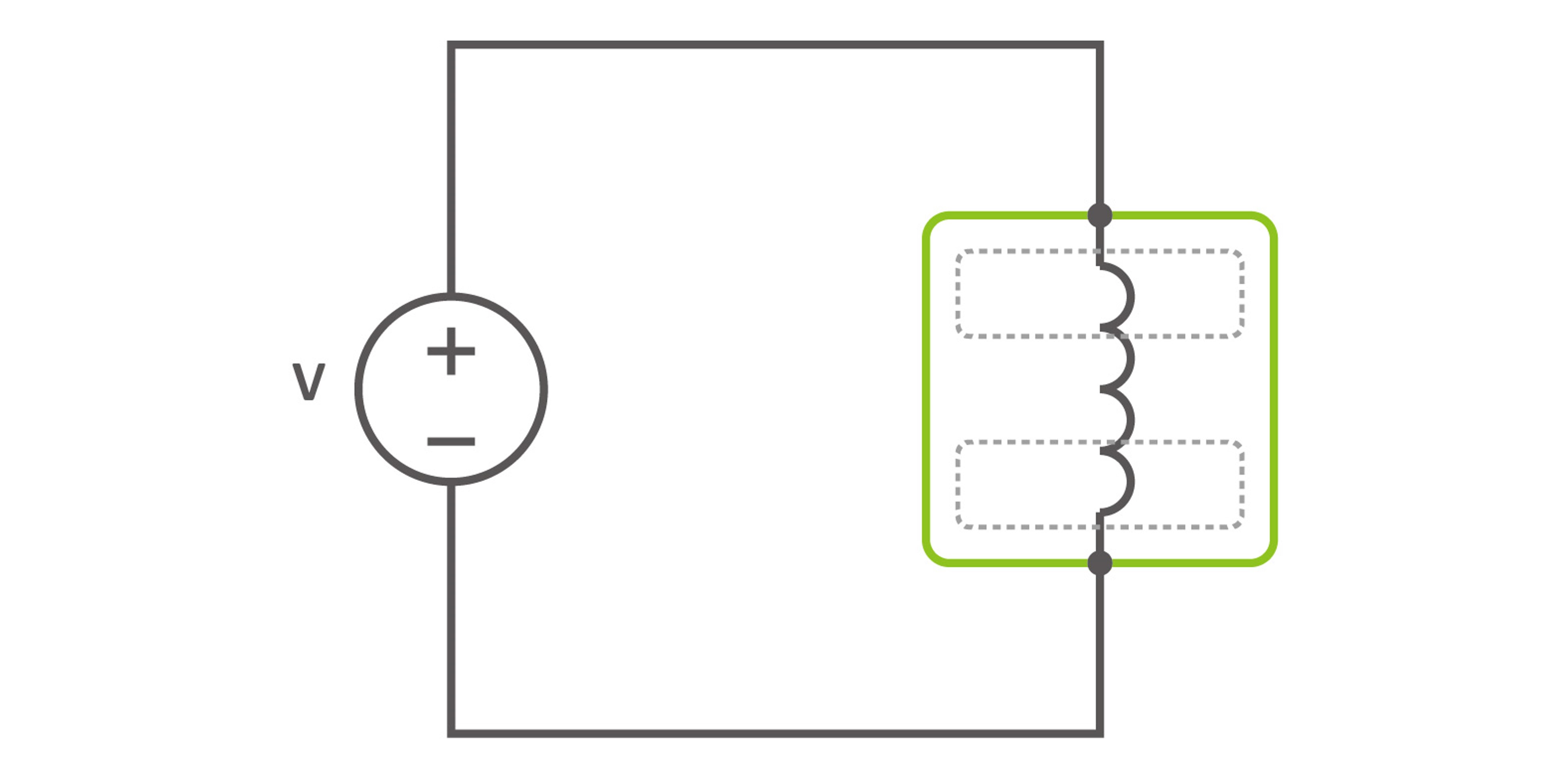
Fig. 2:Working voltage
This operating voltage can originate directly from a voltage source as shown in the diagram, or it can be generated at the terminals of the inductor when the circuit is operating. In either case, the operating voltage of the inductor must adhere to the relationship outlined in formula 1, stemming from Faraday's law of electromagnetic induction.

formula 1:Inductive current-voltage relationship
According to the definition in the North American UL60950 safety standard, the operating voltage is the maximum voltage that the insulation or component under consideration can withstand when the equipment is operating under normal use conditions, and this definition does not include external overvoltages generated during the operation of the equipment.
5、 Definition of Operating Voltage for Coupled Inductors & Common Mode Chokes
Don't confuse operating voltage with isolation voltage or hi-pot testing.
As shown in Fig. 3 , the rated voltage for coupled inductors and common mode chokes typically equals the isolation voltage or hi-pot voltage, which measures the insulation strength between transformer windings or between windings and the enclosure.
Isolation voltage (hi-pot voltage) must be considered separately and is more applicable to isolation transformers rather than single-winding inductors.
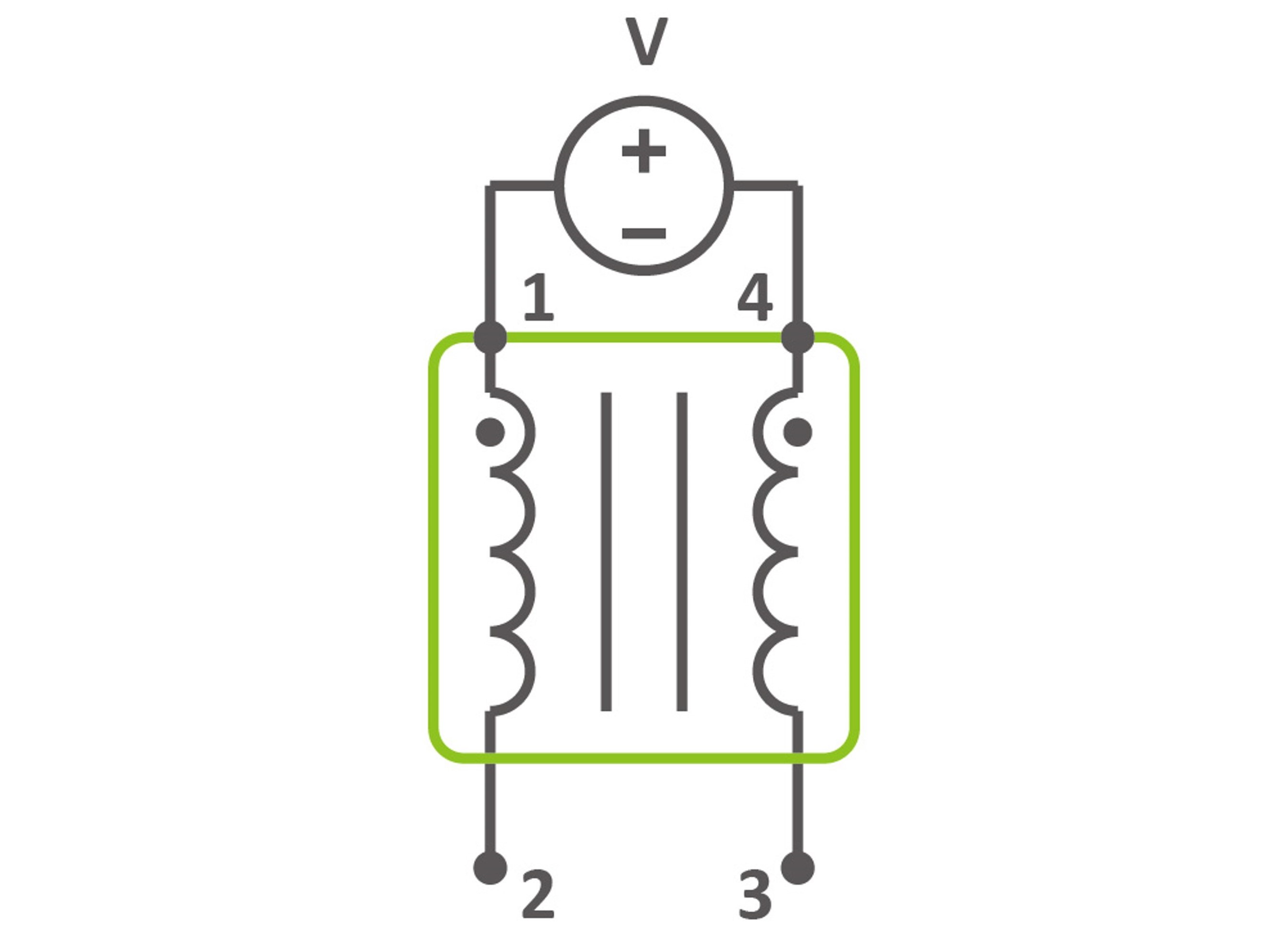
Fig. 3:Hi-Pot measurement of isolation transformers
6、 Definition of Rated Operating Voltage
The rated operating voltage specifies the working voltage that won't damage the insulation of the inductor.
Since repeated overvoltage can sometimes harm insulation, the most conservative rated voltage should be the maximum voltage that can be continuously or repeatedly applied to the terminals of the inductor without damaging the insulation.
For example, for a square wave inductor voltage as shown in Fig. 4, the rated operating voltage equals or exceeds the square wave voltage, guiding the selection of the inductor.
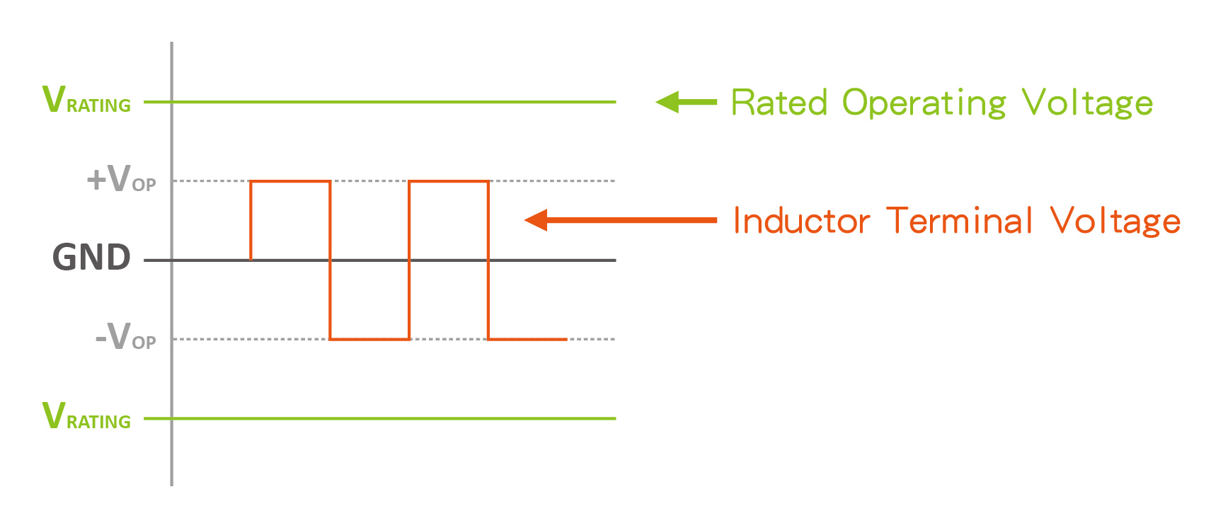
Fig. 4:Inductance rating ≧ Expected voltage
Methods for Validating Rated Operating Voltage :

Explanation : The application of voltage depends on various factors, and overvoltage may result in component failure, overheating, and burnout. This voltage is determined based on breakdown voltage testing and may vary under different circuit conditions. Users need to verify if it's being used correctly.
Example of HI-POT Testing:
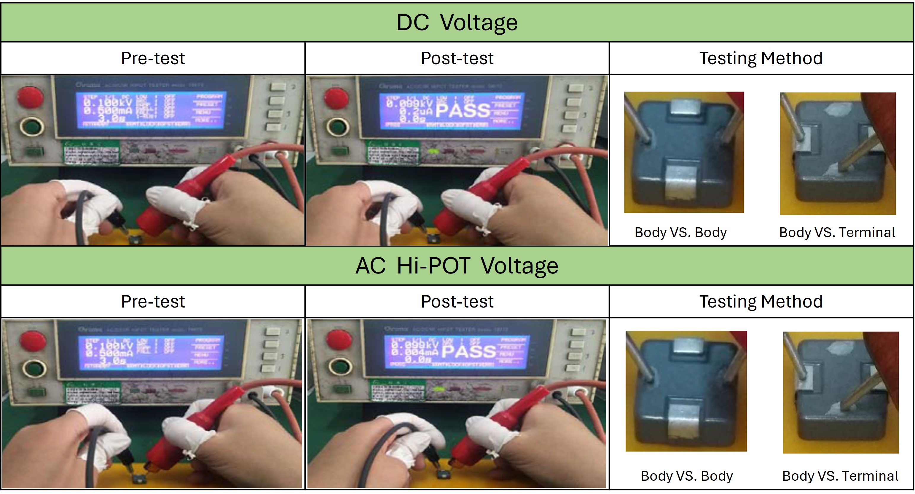
Example of Surge Current Testing :

Example of Insulation Resistance Testing :

Currently, few industry peers define rated voltage specifications in their product specifications. This is primarily because measuring rated voltage requires the use of application-specific test boards to assess the actual voltage capabilities of the product. Different product designs, applications, and PCB layouts can all influence the rated voltage capability.
Although there are many challenges and issues with defining rated voltage for inductor products, the good news is that GOTREND has already developed highly precise measurement technologies capable of setting the rated voltage for inductors.
Related articles :
• How to Calculate Inductor Ripple Current ΔIL?
• What requirements should the solder joints of lead-free solder meet?
• GOTREND【GSFH Series】high-current molded inductors-Excellent performance, high stability, versatile applications.
 GOTREND Technology Co., Ltd.


