Structural Characteristics of Molded Inductors
![]() 2025.11.4
2025.11.4
 Articles
 GOTREND
.jpg "串聯與並聯的基本概念 - 封面")
A molded inductor integrates the winding coil and magnetic powder into a single structure through compressionmolding technology.It features high saturation current, low magnetic leakage, and excellent reliability, making it a mainstream solution forapplications such as automotive electronics, servers, and fast-charging consumer devices.During manufacturing and end-use, cracks in the inductor body are occasionally observed. Although the impact of such cracks is often minor, they represent a true test of a manufacturer’s comprehensive
一、 CONTENT
1. Structural Characteristics of Molded Inductors
A molded inductor is a fully integrated magnetic component in which an enameled copper wire coil is placed inside amold and filled with magnetic powder materials such as Fe-Si, Fe-Si-Al, or Fe-Ni. The powder is then pressed, sintered, demagnetized, and plated, forming a solid, monolithic magnetic structure.While this structure enhances mechanical strength and heat dissipation, it also means that any microcracks or air voidswithin the powder material, if not properly controlled, may propagate into visible cracks during thermal cycling.
2.Main Causes and Preventive Measures for Molded Inductor Cracking
(1) Thermal Stress Mismatch
-
Cause:
The molded inductor consists of a copper coil and magnetic powder, two materials with significantly different
coefficients of thermal expansion (CTE).
Copper: ~17 × 10⁻⁶ /K
Magnetic powder (Fe-Si, Fe-Si-Al, etc.): ~12–15 × 10⁻⁶ /K
During processes such as reflow soldering, thermal cycling, or high-temperature aging, repetitive expansion andcontraction occur between the coil and powder.If the powder density is uneven or microcracks exist internally, thermal stress tends to propagate along these weakpoints, leading to visible cracks.
-
Prevention:
Material design: Use powder materials with similar CTE values and maintain consistent batch quality.
Structural design: Maintain proper distance between the coil and outer surface to reduce stress paths.
Process control: Apply slow heating and cooling profiles (heating rate < 3 °C/s).
.png)
(2) Moisture and Volatile Gas Pressure
-
Cause:
If magnetic powder or binder absorbs moisture, residual water remains inside the material. During baking or reflow, water vaporizes and expands, generating internal gas pressure that can cause micro-voidexpansion or localized bursting, a common mechanism behind surface bulging or internal cracking.
-
Prevention:
Material storage: Keep powder and binders sealed in a dry environment; exposure time < 24 hours.
Pre-bake before molding: Preheat powder at 100–120 °C for 2–4 hours to remove moisture.
Post-molding bake: Use gradual temperature ramps to avoid vapor expansion.
Equipment control: Regularly calibrate oven temperature uniformity (±3 °C).
Inspection: Implement moisture content testing to ensure < 0.05%.
(3) Uneven Molding Density
-
Cause:
During molding, if the mold design is unbalanced, pressure distribution uneven, or powder flow poor, some regionsmay have lower density.These low-density areas become structural weak zones, prone to cracking during demolding, baking, or mechanicalstress.
-
Prevention:
Mold design: Optimize powder flow channels and add vents to prevent dead zones.
Pressing process: Use servo presses or progressive pressure control for uniform compression.
Powder management: Control particle size distribution to improve flowability.
Process monitoring: Check molded density for each batch; deviation ≤ ±0.03 g/cm³.
Quality validation: Use X-ray or CT scanning to verify internal density uniformity.
.png)
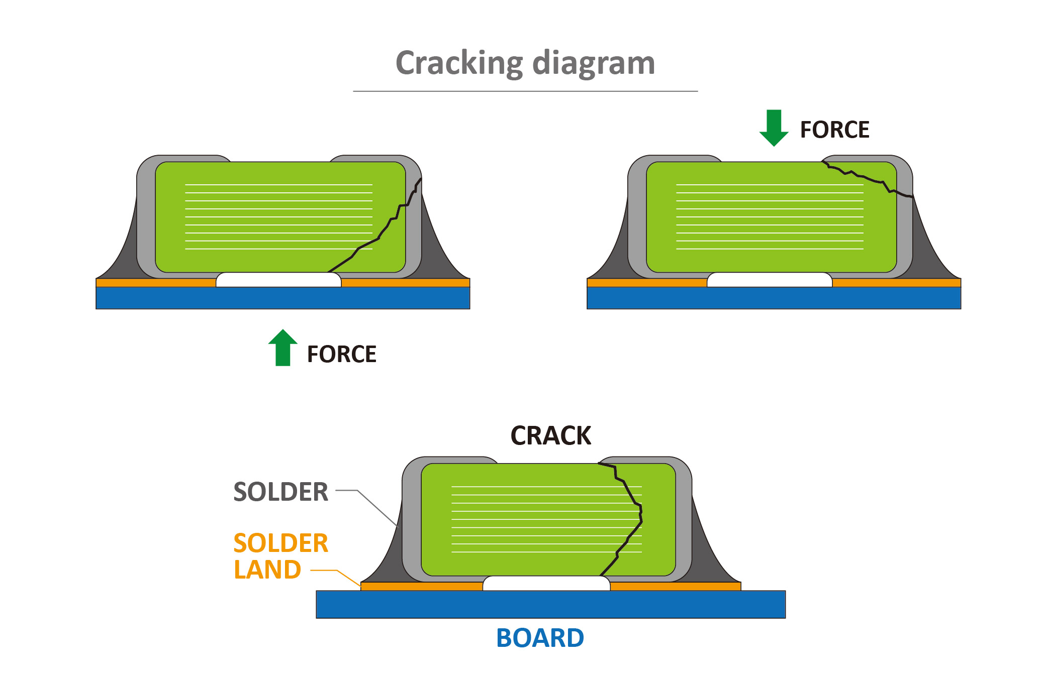
(4)External Mechanical Stress
-
Cause:
Although molded inductors are monolithic, the outer shell remains a brittle magnetic material. Excessive external forces during assembly, handling, or testing (e.g., pick-and-place nozzle impact, PCB warpage,tight packaging) can lead to corner or bottom cracks.
-
Prevention: