How to Eliminate Inductor Noise in Electronic Circuits?
 2026.7.18
 Articles
 GOTREND
Q & A
Q: What are the main audible symptoms of inductor noise in a circuit?
A: The noise mainly appears as a low-frequency “buzzing” sound or a sharp high-frequency “whining” sound. Under certain operating conditions, an impact-like “tapping” noise may also occur. When the load changes, the noise level may fluctuate, becoming louder or quieter.
Q: Why does an inductor generate audible noise? What is the core physical mechanism?
A: The fundamental mechanism is that alternating current generates electromagnetic force, which causes mechanical vibration in the magnetic core and coil of the inductor. The vibration is then transmitted through the surrounding medium and becomes audible sound that can be perceived by the human ear.
Root Causes: Why Do Inductors Generate Audible Noise?
Audible noise from an inductor is essentially a physical phenomenon caused by the coupling of electromagnetic effects and mechanical vibration. The following section analyzes the issue from three major vibration sources and related circuit factors.
Three Major Sources of Vibration
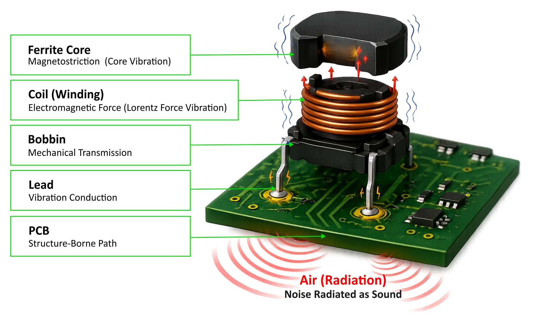
(1) Magnetostriction Effect:Magnetic core materials undergo nanoscale to microscale dimensional changes under an alternating magnetic field. This repeated expansion and contraction generates mechanical vibration. A typical symptom is a low-frequency “buzzing” sound at the line frequency or switching frequency.
(2) Electromagnetic Force Vibration of the Coil:
Lorentz force exists between adjacent conductors. When the current changes, the conductors generate mechanical vibration due to mutual attraction or repulsion. This is often expressed as a sharp high-frequency “whining” sound, which varies with the current level.
(3) Structural Looseness and Resonance:
Assembly gaps may exist between the magnetic core, coil, and bobbin. At certain frequencies, these gaps may trigger resonance and amplify the vibration amplitude. A typical symptom is that the noise level increases or decreases as the load changes.
[Complete Vibration Transmission Path]
Vibration may originate from the joint area of the magnetic core, then be conducted through the coil to the bobbin, further transmitted to the PCB through the terminals, and finally radiated through the air as audible noise.
[Key Insight]
Solving inductor noise problems requires a combined approach from three dimensions: material selection, structural reinforcement, and damping design. The objective is to block both the generation and transmission of vibration.
2. Three Circuit Factors That Make Noise More Noticeable
(1) Switching Frequency Falls Within the Audible Range:The audible frequency range of the human ear is approximately 20 Hz to 20 kHz. If the PWM switching frequency of the power supply falls within this range and the vibration energy is sufficient, the noise can be clearly perceived.
(2) Excessive Current Ripple Caused by Load Transients:
When the load suddenly increases or decreases, the inductor current may experience significant transient variation. The larger the ripple current (ΔI), the greater the fluctuation in electromagnetic force, which further intensifies mechanical vibration and makes the noise more obvious.
(3) The Inductor Approaches Magnetic Saturation:
When the current is too high, the magnetic core enters saturation and its permeability drops sharply. This causes sudden changes in the inductor characteristics, resulting in abnormal and larger electromagnetic force fluctuations, eventually leading to obvious mechanical vibration and noise.
3. Countermeasures: Six Key Solutions
From theoretical analysis to practical application, the following section systematically explains six key approaches to solving inductor noise issues from the perspectives of material selection, structural optimization, process improvement, and circuit control.Countermeasure A: Increase the Switching Frequency — Circuit Design Level
Core Principle:Ultrasonic threshold avoidance. By increasing the PWM frequency above 20 kHz, the operating frequency moves beyond the human audible range of 20 Hz to 20 kHz, thereby eliminating the perceived “buzzing” noise from the source.
Application Example:
An LED driver power supply originally used 1 kHz PWM dimming and had obvious inductor whining. After improvement, the frequency was increased to 25 kHz. The audible noise disappeared completely, while dimming smoothness and power conversion efficiency were not negatively affected.
Engineering Trade-Offs:
Higher switching frequency increases MOSFET switching losses, so thermal design must be optimized. At the same time, high-frequency signals may introduce EMI concerns, requiring reassessment of the EMC filtering solution.
Countermeasure B: Reinforce the Inductor Structure — Process Level
Core Principle:By physically eliminating looseness and microscopic gaps between the magnetic core, coil, and bobbin, the source of mechanical vibration can be suppressed. This fundamentally reduces the transmission path of vibration to the outside.
Case Example:
For a DC-DC module with abnormal noise under full load, epoxy resin was used to fill the joint areas. After improvement, the noise was reduced by more than 80%, and the structural stability was significantly improved, effectively resolving the “tapping” noise issue.
Implementation Points:
The adhesive must have excellent heat resistance and electrical insulation properties. During dispensing, the heat dissipation surface of the inductor must be avoided to prevent excessive temperature rise that could affect product performance and service life.
Countermeasure C: Reduce Current Ripple — Parameter Optimization Level
Core Principle:Ripple current (ΔI) is the direct cause of electromagnetic force fluctuation. Formula: ΔI = (Vin - Vout) × D / (L × Fsw). The smaller the ΔI, the weaker the vibration and noise.
Test Example:
When the inductance was increased from 10 μH to 22 μH, the ripple current dropped from 2 A to 0.8 A, and the inductor whining was significantly reduced. A similar effect can also be achieved by increasing the switching frequency (Fsw).
Design Trade-Offs:
Increasing the inductance value L may increase component size and cost, and may also reduce the dynamic response speed of the circuit. Therefore, the best balance must be found among ripple suppression, size, cost, and transient performance.
Countermeasure D: Avoid the Resonance Point — System Level
Core Principle:As a mechanical structure, an inductor has its own natural mechanical resonant frequency. If the circuit switching frequency coincides with this frequency, vibration can be sharply amplified and produce strong whining noise. The key solution is to actively adjust the switching frequency parameters so that they move away from the inductor’s resonance range.
Practical Example:
The output filter inductor of an audio power amplifier had severe whining at around 14 kHz. By fine-tuning the PWM controller parameters and increasing the switching frequency from 14 kHz to 16 kHz, the resonance point was successfully avoided and the audible noise disappeared completely.
Key Considerations:
Professional instruments are required to accurately identify the actual mechanical resonance frequency of the product. The frequency adjustment range is limited, and the final frequency must remain within the controller IC specifications and the stable operating range of the overall circuit.
Countermeasure E: Select Low-Magnetostriction Materials — Material Selection Level
Core Principle:Different magnetic core materials have significantly different magnetostriction coefficients. Selecting materials with weaker magnetostriction can directly reduce microscopic deformation of the magnetic core under an alternating magnetic field, thereby reducing vibration and noise radiation.
Application Example:
A charger originally used a conventional iron powder core and had noticeable noise under full load. After replacing it with a Sendust core or a low-loss ferrite core, the overall noise level was significantly improved and met the requirements of a quiet design.
Implementation Points:
When changing materials, the permeability, saturation flux density, and loss characteristics of the inductor must be revalidated. The procurement feasibility and cost increase of the new material must also be considered.
Countermeasure F: Add Soft-Start / Slew-Rate Control — Control Strategy Level
Core Principle:During circuit startup or sudden load changes, rapid current transitions generate impact-type electromagnetic force and may cause abnormal noise. By using hardware or firmware methods to make the current rise gradually, this type of impact vibration can be avoided from the source.
Application Example:
A motor drive circuit generated a “click” sound when the current jumped instantly from 0 A to 5 A. After adding a 200 ms soft-start program in the control firmware, the current rose smoothly, and the impact noise during startup was completely eliminated.
Key Points:
The soft-start time must be adjusted according to the application scenario. If the time is too long, it may affect the user experience. This method mainly improves startup or transient noise, and has limited effect on steady-state operating noise.
Quick Troubleshooting Procedure
Through a systematic process of listening, frequency identification, and operating-condition checking, the root cause of inductor noise can be quickly located. By combining material, structural, and parameter optimization, a closed-loop corrective action can be established.
Step 1 — Locate the Noise Source:
Confirm which inductor is generating the noise, and determine whether it is a low-frequency “buzzing” sound or a high-frequency “whining” sound.
Step 2 — Analyze the Frequency:
Use the FFT function of an oscilloscope to confirm whether the switching frequency falls within the 20 Hz to 20 kHz audible range.
Step 3 — Check the Operating Condition:
Confirm whether the noise only occurs under specific conditions, such as light load, full load, startup, or dimming.
Step 4 — Identify the Root Cause:
Low-frequency “buzzing” → check magnetostriction and magnetic core looseness.
High-frequency “whining” → check coil electromagnetic force and excessive ripple current.
Noise level changes with load variation → check resonance, saturation, and soft-start parameters.
High-frequency “whining” → check coil electromagnetic force and excessive ripple current.
Noise level changes with load variation → check resonance, saturation, and soft-start parameters.
Step 5 — Apply the Appropriate Corrective Action:
Select the most suitable solution from the six countermeasures above.
Step 6 — Verify the Result:
After improvement, key indicators such as efficiency, temperature rise, and EMI must be revalidated to ensure that the overall system still meets the required specifications.
Conclusion
Inductor noise is science, not mystery. It is essentially a physical phenomenon caused by the coupling of electromagnetic effects and mechanical vibration. Its generation, transmission, and suppression all follow clear mechanisms and engineering principles.
• Avoid it when possible:
Increase the switching frequency to move the operating frequency away from the frequency range most sensitive to human hearing, thereby reducing perceived noise interference.
• Reinforce it when necessary:
Use physical methods such as magnetic core and winding reinforcement, adhesive dispensing, or structural fixing to suppress vibration generation and transmission from the source.
• Reduce it at the source:
Optimize circuit parameters to reduce current ripple and add soft-start mechanisms to lower the energy that drives vibration.
[Important Reminder]
Any corrective action may affect circuit performance. After improvement, the electrical characteristics of the product must be revalidated, with particular focus on efficiency, temperature rise, and EMI, to ensure that the overall system meets the required specifications.
• Avoid it when possible:
Increase the switching frequency to move the operating frequency away from the frequency range most sensitive to human hearing, thereby reducing perceived noise interference.
• Reinforce it when necessary:
Use physical methods such as magnetic core and winding reinforcement, adhesive dispensing, or structural fixing to suppress vibration generation and transmission from the source.
• Reduce it at the source:
Optimize circuit parameters to reduce current ripple and add soft-start mechanisms to lower the energy that drives vibration.
[Important Reminder]
Any corrective action may affect circuit performance. After improvement, the electrical characteristics of the product must be revalidated, with particular focus on efficiency, temperature rise, and EMI, to ensure that the overall system meets the required specifications.