Fundamentals of Series and Parallel Connections
![]() 2025.3.5
2025.3.5
 Articles
 GOTREND Technology Co., Ltd.

1. What Is a Series Connection?
A series connection is a circuit configuration in which multiple components or coils are connected sequentially along a single path. Each connection point is referred to as a node, and only two components can be connected at each node. This type of connection is referred to as a series circuit configuration.
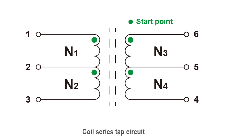
In series-connected coils, when coils are wound in a series configuration for transformer winding applications, one or more taps can be introduced in the coil. This approach allows different coil turns to meet the varied inductance requirements of a circuit. This winding technique is commonly known as tapping.
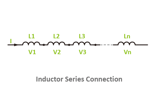
For inductors in series, connecting multiple inductors in a series configuration increases the total inductance, raises the impedance, and reduces the current-carrying capacity, much like the effect of resistors connected in series.
2. What Is a Parallel Connection?
A parallel connection is a circuit configuration in which multiple components or coils are connected such that their ends are linked to the same two nodes. This arrangement is called a parallel configuration.
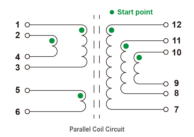
For parallel-connected coils, when coils are wound in parallel or the number of wire strands is increased, the inductance value remains unchanged. However, the impedance decreases, and the current-carrying capacity increases.
The effect of parallel inductors is similar to that of resistors connected in parallel.
3.The Mutual Inductance Effects in Series and Parallel Inductor Configurations
Inductors exhibit mutual inductance effects, which must be considered in calculations to determine whether mutual inductance is present. The configurations can be classified as follows:
• Mutual Inductance in Series Connections :
(1) Series Without Mutual Inductance :
In a series circuit without mutual inductance, the total inductance is equal to the sum of the individual inductances.
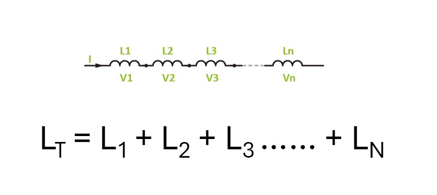
Assuming an inductance value of L₁ = 10 mH, L₂ = 5 mH, L₃ = 7 mH, L₄ = 8 mH, and L₅ = 6 mH, the total inductance in a series circuit without mutual inductance is calculated as follows:
Lᴛ = L₁ + L₂ + L₃ + L₄ + L₅
= 10 + 5 + 7 + 8 + 6 = 36 mH
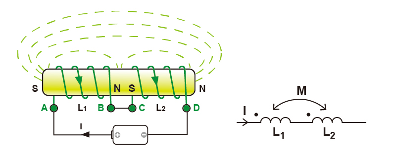
(2) Series With Mutual Inductance :
When inductors with mutual coupling are connected in series, the effect of mutual inductance depends on whether the magnetic flux (or magnetic lines of force) reinforces or opposes each other, affecting the total inductance value.
(a) Series in Phase:
If the magnetic flux directions of the two coils are the same, they reinforce each other, and the mutual inductance value is positive.
Formula : LT = L1 + L2 + 2M
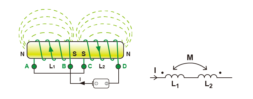
(b) Series Out of Phase :
If the magnetic flux directions of the two coils are opposite, they weaken each other, and the mutual inductance value is negative.
Assuming the inductance values L₁ = 10 mH, L₂ = 5 mH, and mutual inductance M = 2 mH, the total inductance is calculated as follows :
1. Series Connection – Same Direction (Magnetic flux lines align, mutual inductance is positive) :
2. Series Connection – Opposite Direction (Magnetic flux lines oppose, mutual inductance is negative) :
• Mutual Inductance in Parallel Connections :
(1) Parallel Without Mutual Inductance :
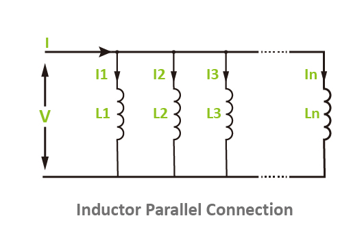
In a parallel circuit without mutual inductance, the total inductance is calculated in the same way as parallel resistors, using the reciprocal sum of the individual inductances.
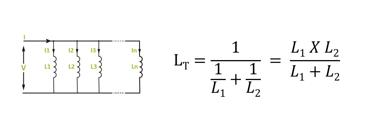
Assuming the inductance values L₁ = 10 mH and L₂ = 5 mH, in a parallel circuit without mutual inductance, the total inductance is calculated as follows :
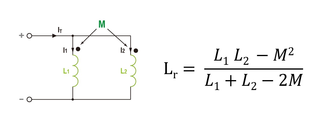
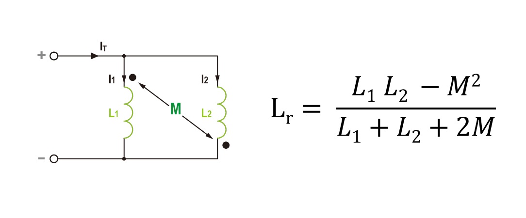
(2) Parallel With Mutual Inductance:
When mutual inductance is present in a parallel circuit, magnetic flux in the same direction enhances the total magnetic flux, while flux in the opposite direction reduces it.
(a) Parallel in Phase : If the magnetic flux directions of the two coils are the same, they reinforce each other, and the mutual inductance value is positive.
(b) Parallel Out of Phase : If the magnetic flux directions of the two coils are opposite, they weaken each other, and the mutual inductance value is negative.
Assuming the inductance values L₁ = 10 mH, L₂ = 5 mH, and mutual inductance M = 2 mH, in a parallel circuit with mutual inductance, the total inductance is calculated as follows:
1.Parallel – Same Phase (Mutual inductance is positive) :
= (10 × 5 − 2²) / (10 + 5 − 2(2)) = 4.18 mH
2.Parallel – Opposite Phase (Mutual inductance is negative) :
= (10 × 5 − 2²) / (10 + 5 + 2(2)) = 2.42 mH
Related articles :
• Does a power inductor require polarity distinction?
• GNLS Series Ferrite-Wound Inductors - The Best Choice for Efficient Power Management
• What is the Dot Convention?