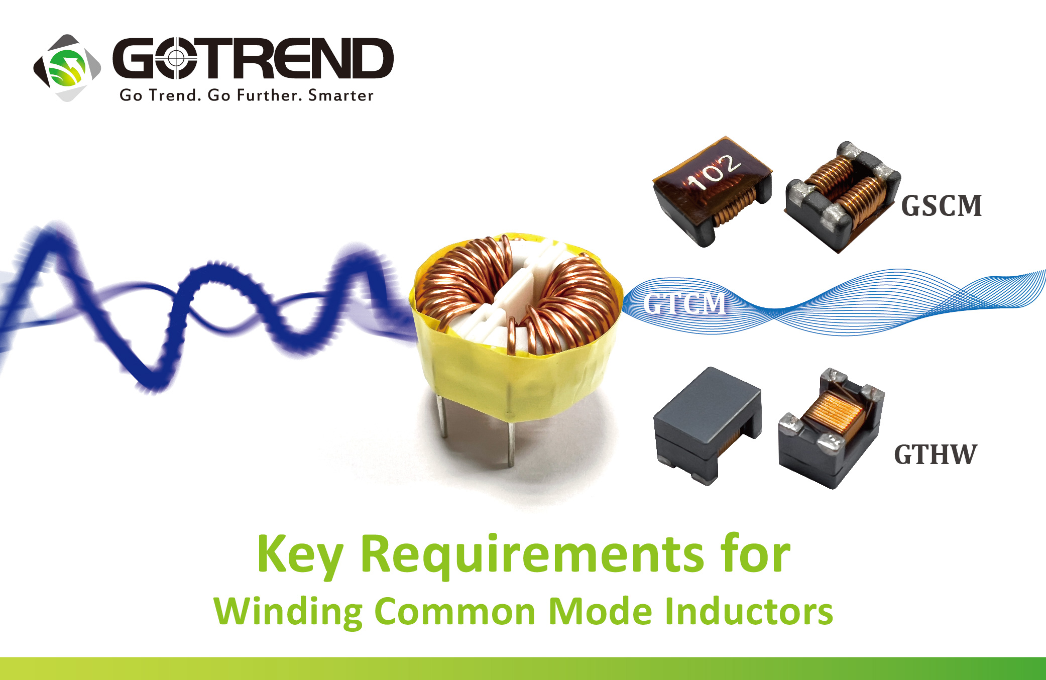
Key requirements for winding common mode inductors
![]() 2024.8.14
2024.8.14
 Articles

Common mode inductors are a regular product at GOTREND and are widely used in electronic circuits to suppress common mode noise. Proper winding is essential to ensure their performance and stability. Here are the key requirements and considerations:
1、First of all, let's know, what is common mode inductor?
Common mode inductors, also known as Common Mode Filter, is often used in switching power supplies of computers to filter common mode electromagnetic interference signals. In electronic design, common-mode inductors also play the role of EMI filtering, which is used to suppress the electromagnetic waves generated by high-speed signal lines to radiate outward, especially in signal transmission or power supply circuits, and often encounter interference signals applied to both inputs of the circuit (such as signal and ground) at the same time, which may come from external interference sources or other parts of the circuit.
2、Understanding the working principle of common mode inductors.
A、Magnetic Coupling :
Two coils are tightly placed together, creating a magnetic field between them when common mode interference occurs. This field induces a voltage in the coils.
B、Generate opposite signals :
Due to the arrangement and direction of the magnetic fields, the coils generate opposing induced voltages. If a common mode signal induces a positive voltage in one coil, it will induce a negative voltage in the other.
C、Cancel common mode interference :
This design effectively cancels out common mode interference. As the interference passes through the circuit, the opposing induced voltages in the choke reduce the interference energy.
In summary, when operating current flows through two oppositely wound coils, they generate two canceling magnetic fields. At this point, the operating current is affected by the coil's ohmic resistance and leakage inductance damping. If interference signals pass through the coils, the coils exhibit high impedance, producing a strong damping effect that attenuates the interference signals.
3、When winding common mode inductors, keep the following points in mind :
A、The magnetic core within the coil should be insulated from the coil itself, and the two sets of wires wound on the core must also be insulated from each other. This ensures that the coil windings do not break down and short-circuit under transient overvoltage conditions.
B、The coil should be wound as a single layer whenever possible. This reduces the parasitic capacitance of the coil and enhances its ability to withstand transient overvoltage.
C、Typically, it is important to select the appropriate filtering frequency band, with a higher common mode impedance being preferable. When selecting a common mode inductor, refer to the device specifications and choose based on the impedance-frequency curve.
D、Consider the impact of differential mode impedance on the signal when selecting a common mode inductor. Focus particularly on differential mode impedance for high-speed ports.
E、Common mode inductors are usually composed of two closely placed coils. Ensure that the coupling effect between these two coils is strong enough to effectively cancel out common mode interference signals. The physical distance and layout between the coils are crucial for optimal coupling.
F、The two coils in a common mode inductor should be wound in opposite directions. This ensures that when a common mode interference signal passes through, the coils generate opposite induced voltages that cancel out the interference. Correctly positioning the direction and polarity of the coils during winding is essential.
G、The performance of a common mode inductor depends on the number of turns and the winding method of the coils. To achieve the desired common mode suppression effect, the number of turns must be precisely calculated and wound. Additionally, ensure that the winding has uniform turns and good insulation between layers to avoid electrical leakage between the coils and other components.
H、The choice of wire for a common mode inductor is critical to its performance. Typically, magnetic material-coated wire is used to enhance magnetic coupling. The wire gauge should accommodate the current load and layout space constraints, while also considering factors such as self-inductance and resistance.
I、After winding, it is necessary to test and verify the common mode inductor. This includes testing its common mode suppression effect at different frequencies to ensure it meets design requirements and effectively suppresses common mode interference.
In conclusion, winding a common mode inductor requires precise calculations and meticulous design to ensure effective suppression of common mode interference. Proper selection of wire, number of turns, winding method, and ensuring good coupling and polarity are all critical steps.
GOTREND Technology As A Green Enterprise For Global Sustainability
It is stated in our company philosophy that GOTREND enterprise group had the vision of setting up a dream enterprise that work for the sustainable growth, learning, creativity, profitability and happiness of every employee, partners, our customers, investors, and in helping to bring about a better living world. We respect Lifestyles of Health and Sustainability (LOHAS), support actions towards better environmental protections and are committed to design, manufacture and produce energy efficient, environmental friendly products.
Green manufacturing is our belief and all GOTREND products including raw materials, spare parts, solvent, consumables, packing materials, as well as production process are in conformity with WEEE(Waste Electrical and Electronic Equipment 2002/96/EC)and RoHS compliance. GOTREND preferred eco-friendly manufacturing methods and materials.
 GOTREND Technology Co., Ltd.


