Design and Parameter Calculation of Qi Wireless Charging RX Coil
![]() 2024.8.21
2024.8.21
 Articles
The implementation of the Wireless Power Consortium (WPC) Qi standard has enabled a variety of end applications to feature wireless charging capabilities. The size or power requirements of the receiver (Rx) coil may vary depending on the specific application.
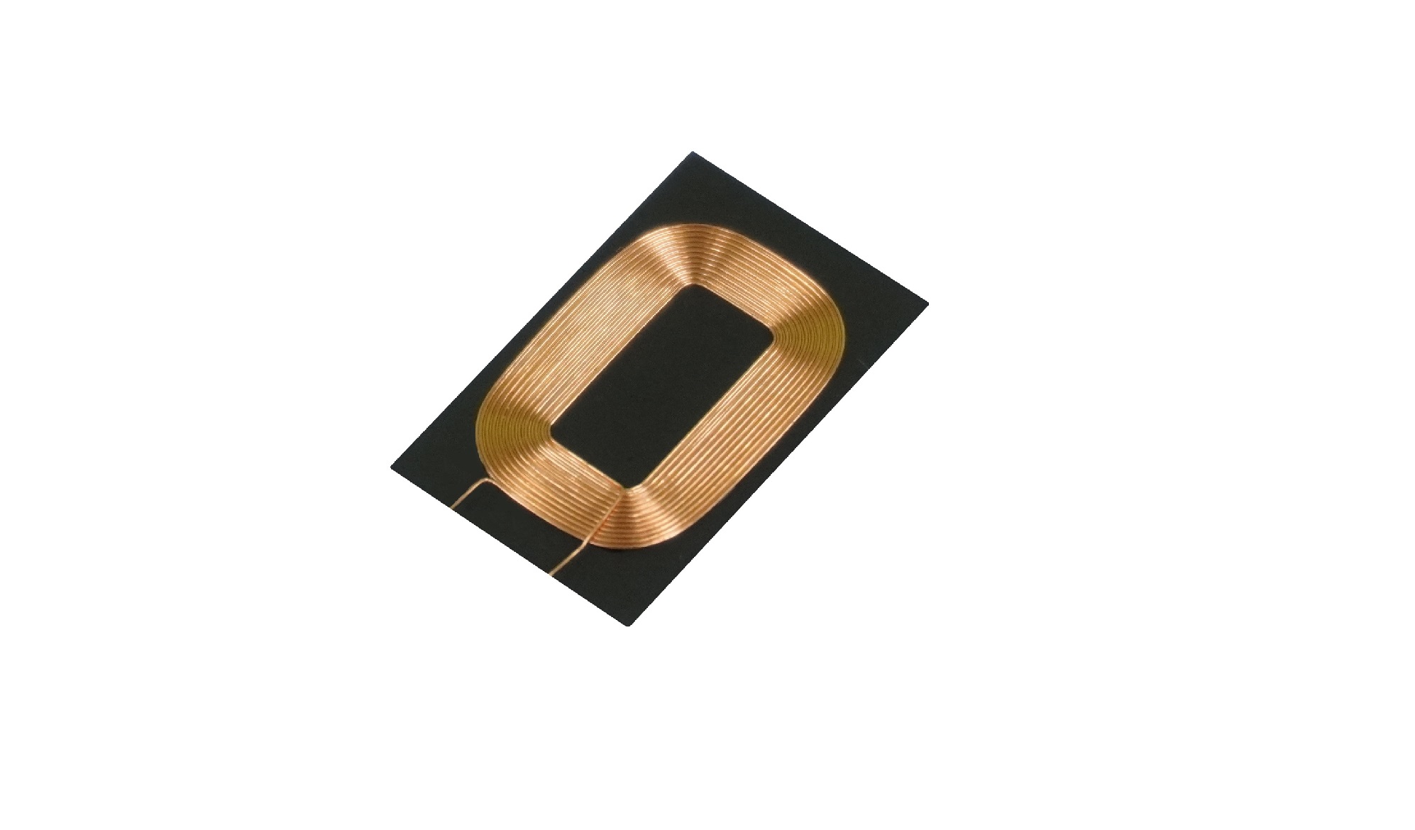
Qi wireless charging technology operates based on the principle of electromagnetic induction to achieve wireless charging. In a Qi charging system, the RX (receiver) coil is a critical component, responsible for receiving the power transmitted from the TX (transmitter) coil.
The structure of a Qi wireless charging RX coil is typically made by winding copper wire into a loop or spiral shape. This design maximizes the reception of the magnetic field emitted by the TX coil, thereby achieving efficient energy transfer. Various factors such as size and shape, materials, frequency, matching, efficiency, and thermal management all influence the overall charging performance.
In summary, designing a Qi wireless charging RX coil is an engineering challenge that requires a comprehensive consideration of multiple factors, balancing energy transfer efficiency, space utilization, cost, and user experience.
1、RX Coil Design Steps
At first glance, wireless charging might seem like a complex engineering feat, but it’s actually more straightforward than it appears. All that’s needed to create a basic wireless charging setup is a transmitter coil and a receiver coil. Let’s get started with a hands-on approach.
The basic steps for designing a wireless charger receiver coil are as follows :
(1)Identify the Need for a Wireless Charger Receiver.
(2) Understand Physical Design Constraints : Consider the X, Y, and Z dimensional limitations of the coil and estimate the interface gap.
(3)Select Parameters : Determine the power required by the load, the expected coupling coefficient between the Tx and Rx coils, and the available space for the Rx coil.
(4)Simulate Circuit Operation : Perform simulations under the best possible conditions for receiving.
(5)Display Load Line Curve : Assess whether the load line curve is acceptable.
(6)Create Specifications : Develop a set of specifications for the receiver coil that can be sent to a magnetic component supplier, and create a Bill of Materials (BOM) for the Rx coil.
(7)Construct and test the prototype on a tester specified by the IC solution company.
(8)Finalize Coil Design.
2、Brief Overview of the Qi Standard System
For the wireless power systems regulated by the Wireless Power Consortium (WPC), magnetic power transfer can be achieved using a simple transformer. Traditional transformers typically consist of a single physical structure where two coil windings are wrapped around a magnetic core material. The magnetic core has a much higher permeability than air (see Figure 1). Due to the use of high-permeability materials in traditional transformers, most of the magnetic flux generated by one coil couples with the other coil. The degree of coupling is measured using the coupling coefficient (k-value), which ranges from 0 to 1.
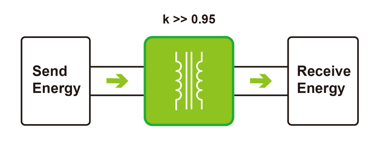
Figure 1. Traditional Transformer with a Single Physical Structure
A dual-coil transformer is defined by the following three parameters:
L11 represents the self-inductance of coil 1.
L22 represents the self-inductance of coil 2.
L12 represents the mutual inductance between coils 1 and 2.
The coupling coefficient between the two coils can be expressed as :
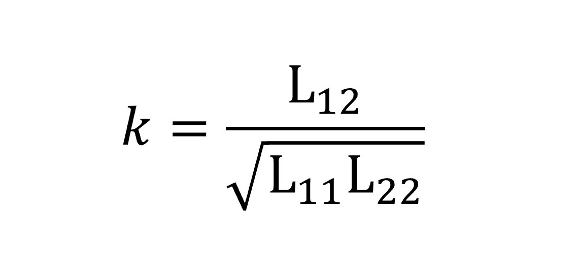
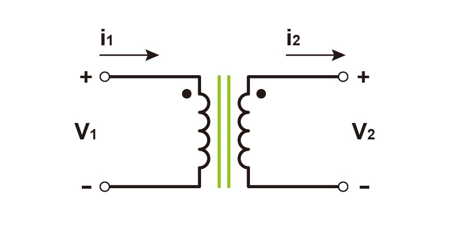
Figure 2. Ideal Model of a Traditional Transformer
Using the coupled inductors shown in Figure 2, the ideal transformer can be modeled. By applying the voltage and current relationships of these inductors, the wave equation for this dual-coil transformer can be derived.
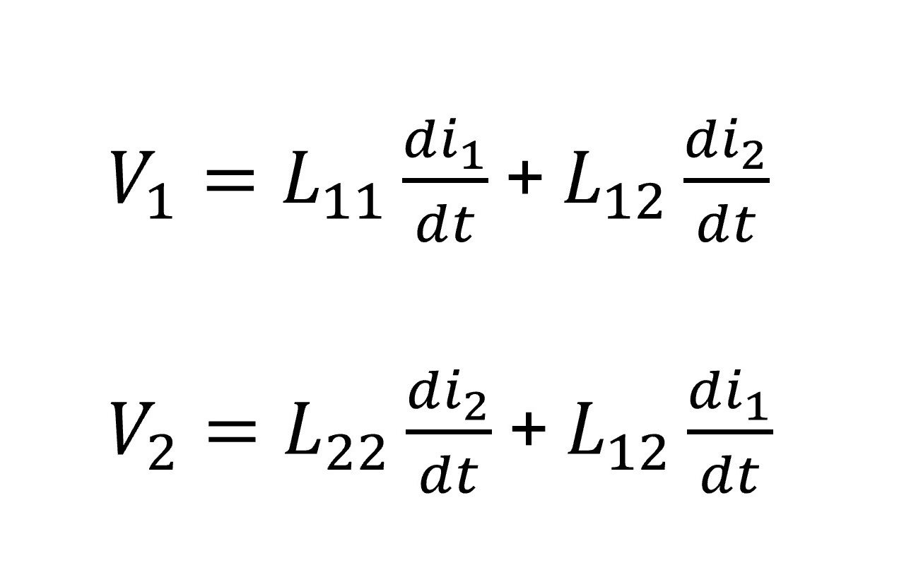
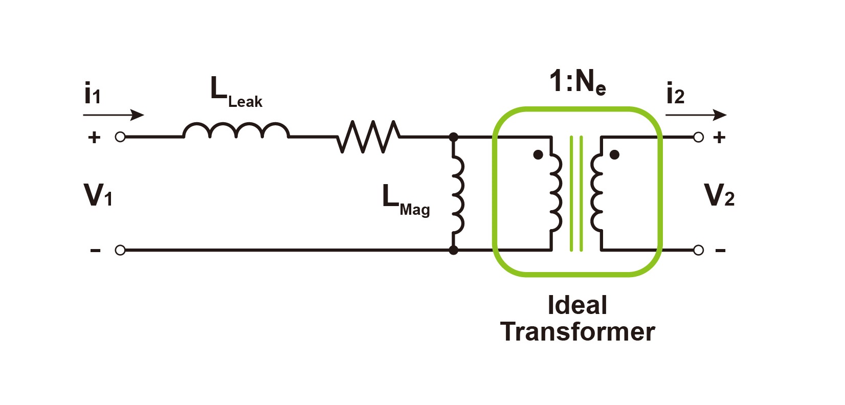
Figure 3. Cantilever Model of a Traditional Transformer
For the convenience of circuit analysis, the model in Figure 2 can be represented using a cantilever model, as shown in Figure 3. In this representation, the magnetic coupling and mutual inductance are simplified into leakage inductance and magnetizing inductance. Through this circuit realization, we can understand the physical nature of this coupling. For an ideal transformer, the turns ratio can be calculated using the following equation:
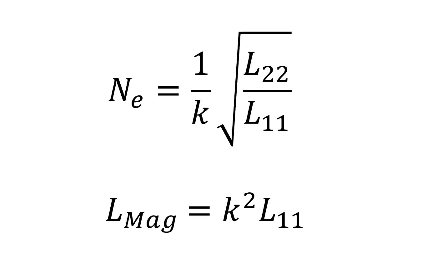
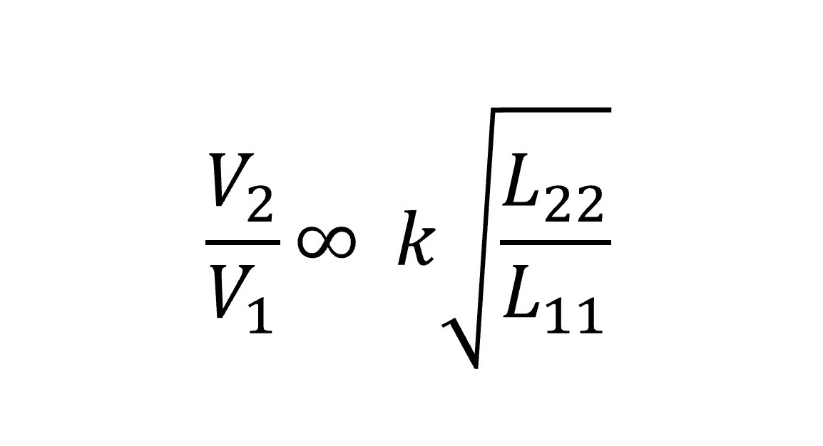
In a strongly coupled system, the leakage inductance percentage of the magnetizing inductance is very small, so this parameter can be neglected when calculating the first approximation. Besides high coupling, the series resonant capacitors used in the Qi standard system also reduce the impact of leakage inductance. Therefore, the first approximation of the voltage gain from the primary coil to the secondary coil is:
The transformer in a Qi standard system is composed of two separate physical components :
The transmitter (Tx) and the receiver (Rx), each with its own isolated coil. When the Tx and Rx are in proximity, they form a coupled inductance relationship, which can be simply modeled as a dual-coil transformer using an air core (see Figure 4). The shielding materials at both ends serve as a magnetic flux shortcut, ensuring that the magnetic flux exists between the two coils. Figure 5 shows a 2D simulation of the magnetic field lines during typical operation.
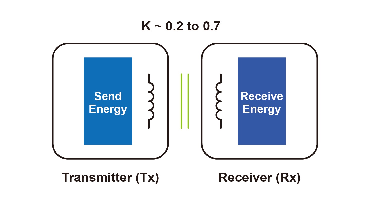
Figure 4. Simplified Inductive Coupling Transformer Using an Air Core
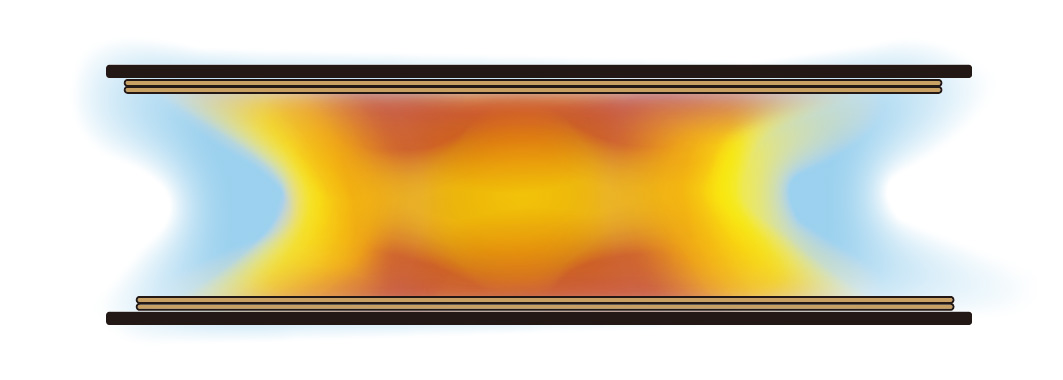
Figure 5. Simulated Magnetic Field Distribution with Current Flowing Through the Coils
In a typical Qi standard system, the coupling coefficient (k) is significantly lower than in traditional transformers. The coupling coefficient for traditional transformers ranges from 0.95 to 0.99, meaning 95% to 99% of the magnetic flux couples to the secondary coil. However, for Qi standard systems, the coupling coefficient ranges from 0.2 to 0.7, meaning 20% to 70% of the magnetic flux is coupled. In most cases, Qi standards employ a series resonant capacitor on the Tx and Rx to mitigate this low coupling issue. This capacitor can compensate for the resonant leakage inductance.
3、The Role of Shielding Materials
Shielding materials serve two primary functions :
(1) They provide a low-impedance path for magnetic flux, preventing interference with surrounding metal objects or components.
(2) They allow for achieving higher inductance values with fewer turns, which reduces coil resistance (since more turns result in higher resistance).
Thick shielding materials capable of absorbing substantial magnetic flux (having a high flux saturation point) can prevent the material behind the Rx coil from heating up. When dealing with Tx or Rx with alignment magnets, thick shielding materials maintain efficiency better than thin ones.
GOTREND offers typical shielding materials that help minimize efficiency loss.
4、Rx Coil Wire Selection
Selecting the appropriate wire for the Rx coil involves balancing cost and performance. For instance, large-diameter wire or Litz wire (two parallel strands) offers higher efficiency compared to small-diameter wire or single-strand wire but comes at a higher cost. Alternatively, a PCB-printed coil may be more cost-effective overall but will have higher equivalent series resistance compared to Litz wire.
5、Selection of Rx Coil Turns
Once the wire and shielding materials are chosen, the number of turns in the Rx coil can be determined based on the desired Rx coil inductance. The coil inductance and coupling determine the voltage gain at the receiver (Rx) rectifier and the overall effective power of the Rx.
The general approach to determining the inductance target is as follows:
(1) Use the A1 type coil of Tx as a basis for primary coil characteristics (e.g., area of 1500 mm2, inductance of 24 µH, primary voltage of 19V).
(2) When the permeability of the shielding material is significantly greater than air (>20), the coil area can effectively represent the coupling coefficient.
(3) Determine the ideal voltage gain based on the average expected rectifier voltage.
For a typical 5V/5W output voltage system design, with a coupling coefficient of around 0.5, a secondary inductance of approximately 10 µH is sufficient to generate the required target voltage.
Note that this scenario applies only to flat coils with single or double layer windings. Special coil structures may not adhere to this principle. To ensure reasonable coupling and efficiency, in a 5W system, the Rx coil area of a wireless charger receiver should be approximately 70% to 80% of the A1 type coil area of the wireless charger transmitter (Tx). This ensures that most designs achieve a coupling coefficient of around 50%, with the distance between the wireless charger transmitter (Tx) and wireless charger receiver (Rx) coils meeting the 5mm specification of the WPC.
This article explains how we can leverage the basic principles of traditional transformers to simplify coil designs in wireless charging systems. However, the ubiquity and characteristics of mobile devices also introduce some unique variations in standard magnetic design approaches. Carefully reading and understanding the coil design content introduced earlier can increase your chances of success on the first attempt. The evaluation methods we have outlined allow you to systematically specify and describe a custom Rx coil.
 GOTREND Technology Co., Ltd.


