Inductor power loss calculation
![]() 2022.10.14
2022.10.14
 Articles
Loss calculations for major power components such as transistors, inductors and transformers in UPS have always been a challenge for customers. To improve the accuracy of the design, it is necessary to provide a proven prescriptive calculation method for the power consumption of the component.
With the continuous improvement of power supply efficiency requirements, the requirements for improving inductance efficiency have also increased rapidly, which is the result of the increase in the output current of the power supply. At the same time, the industry is making further efforts to reduce heat dissipation from the power supply, which has a direct impact on the overall power efficiency. Reducing the generation of heat is especially important for laptop /PC/Server users.
Inductive losses are mainly composed of core losses and coil losses, which include hysteresis losses and eddy current losses. For powder cores, the eddy current loss is almost negligible due to the large insulation impedance between the magnetic materials.
1. Inductor power loss calculation
The power loss of an inductor is determined by the basic formula :

Each quantity of the formula is described below.
• 1.1 Pcore
The sum of the calculations /or measured core losses are usually provided directly by the Inductive components supplier. If not, the core loss can be calculated using a formula. Due to the influence of the test frequency, measuring core losses and achieving repeatability results is a tedious task. General formula for core loss calculation of ferrite core :

Where :
• K1 = core material constant• f = frequency (kHz)
• B = peak magnetic flux density (kGauss)
• x = frequency index
• y = magnetic flux density index
• Ve = core effective volume (cm³)
Core loss can be calculated by inputting the unique K1 constant for each core material, along with the corresponding frequency and flux density exponents.
• 1.2 Pdcr
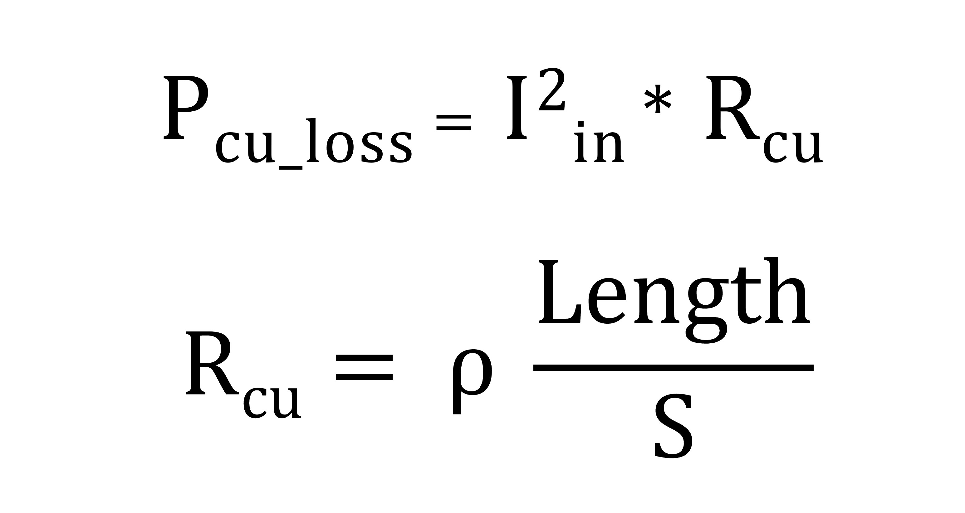
Coil losses caused by DC resistance are relatively easy to calculate.
It's determined by this basic formula (regardless of the effect of current ripple on copper loss) and is calculated as follows :

Where :
• Length : refers to the winding length
• S : represents the winding radius
• ρ : stands for the resistivity of the copper conductor (at 20°C, ρ = 1.678Ω/m)
• Since the operating temperature of inductors is typically higher than 20°C, the resistance of the inductor must be adjusted accordingly.

In the formula, α is the temperature coefficient, α=0.00393/°C, and ∆t is the desired temperature rise.
Therefore, the formula for inductor copper loss needs to be corrected to :

• 1.3 Pacr
Coil losses caused by AC resistance are difficult to calculate because the AC impedance value of the coil is not always obtained from the electromagnetic supplier.
Pacr is determined by the following formula :

Where :
• Irms = rms of the inductor peak-to-peak ripple current
• ACR = AC resistance of the inductor
Inductor suppliers are typically able to provide information on inductor power losses for most of their products. To speed up the design process for engineers using inductors, GOTREND has created a calculator that estimates the loss of inductor cores and coils.
The calculator is based on the formula :

This application document describes the basic formula for determining inductor power loss. At the same time, it also mentions that in order to reduce the generation of heat and thus improve the overall efficiency, it is necessary to understand how the inductor power loss is generated.
Related articles :
• APPLE MagSafe tangle dancing with Qi2 MPP
• What is copper loss? What is the skin effect ? The difference between Isat and Irms
• What is an inductor?
 GOTREND Technology Co.,Ltd


